Honda ZR-V (2023 – 2025) – fuse and relay box diagram

Honda ZR-V (2023 – 2025) – fuse and relay box diagram

Year of production: 2023, 2024, 2025


This article focuses on the third-generation Honda HR-V (North American version) / Honda ZR-V, available from 2022 to the present. It includes fuse box diagrams for the 2023 and 2024 Honda HR-V (US) / ZR-V models, provides details on the locations of the fuse panels within the vehicle, and explains the function and layout of each fuse.


Passenger Compartment Fuse Panel

Fuse Box Location

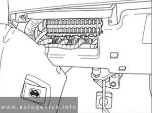
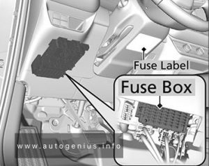
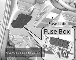
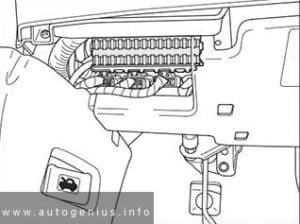
The fuses are located under the dashboard. Fuse locations are shown on the label under the steering column.

Honda ZR-V - fuse and relay box location - passenger compartment
Honda ZR-V – fuse and relay box location – passenger compartment


Fuse Box Diagram

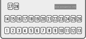
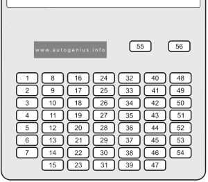
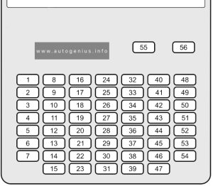
Honda ZR-V - fuse and relay box diagram - passenger compartment
Honda ZR-V – fuse and relay box diagram – passenger compartment


Assignment of the fuses in the instrument panel 

Amps Circuit Protected
1 20A P/W DR
2 20A P/W AS
3 20A P/W RR R
4 20A P/W RR L
5 10A OPTION
6 10A SRS
7 10A T/G MTR
8 10A ZR-V: IDAS / HUD
9 20A ZR-V: FR ACC SOCKET
10 20A DOOR LOCK
11 10A METER
12 10A ST CUT RLY
13 10A OPTION2
14 10A OPTION6 (VB SOL)
15 10A DR DOOR UNLOCK
16 20A SUNROOF
17 10A ZR-V: SBW
18
19
20 10A ZR-V: RR FOG
21 20A CARGO ACC SOCKET
22 10A SMART
23 10A DR DOOR LOCK
24
25 10A IMG
26 10A SRS
27 10A ACG
28 10A ABS/VSA
29 20A FUEL PUMP
30 10A L SIDE DOOR UNLOCK
31 10A R SIDE DOOR UNLOCK
32
33 10A USB CHG
34
35
36 20A ZR-V: PTG CLOSER
37 20A HR-V (US): E-PTL
38 20A ZR-V: IGA2
39 10A R SIDE DOOR LOCK
40 20A P SEAT REC / RR HI
41 20A P SEAT SLIDE / FR HI
42 10A ZR-V: IG1 MON
43 10A A/C
44 10A DRL
45 10A ACC
46 10A ACC KEY LOCK
47 10A L SIDE DOOR LOCK
48 20A HR-V (US): H/SEAT
ZR-V: FR H/SEAT
49 20A ZR-V: AS P SEAT REC
50
51 20A ZR-V: RR H/SEAT
52 20A HR-V (US): E-DPS
53 20A ZR-V: AS P SEAT SLIDE
54 10A OPTION 1 / FUEL LID
55
56

Engine Compartment Fuse Box

Fuse Box Location

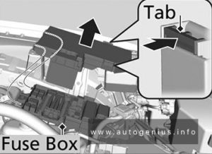
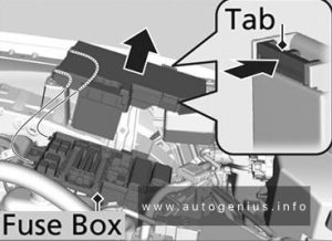
The fuse box is located near the battery. Push the tabs to open the box. Fuse locations are shown on the fuse box cover.

Honda ZR-V - fuse and relay box location - engine compartment
Honda ZR-V – fuse and relay box location – engine compartment


Fuse Box Diagram

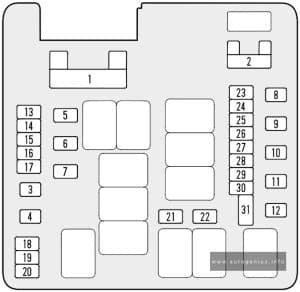
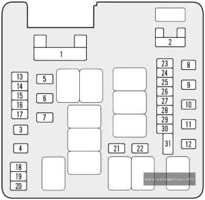
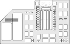
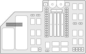
Honda ZR-V - fuse and relay box diagram - engine compartment
Honda ZR-V – fuse and relay box diagram – engine compartment


Assignment of the fuses in the engine compartment

Amps Circuit Protected
1 125A BATTERY
2-1 40A ZR-V: A/C PTC1
2-2 40A
2-3 60A F/BOX OPTION
2-4 40A
2-5 40A F/BOX OPTION2
2-6 30A
2-7 60A F/BOX MAIN
3-1 30A
3-2 30A
3-3 70A
3-4 30A RR DEFROSTER
3-5 40A ZR-V: PTG MTR
3-6 30A ZR-V: A/C PTC3
3-7 40A HTR MTR
4-1 30A ZR-V: ESB
4-2 40A ABS/VSA MTR
4-3 30A ZR-V: RFC
4-4 30A ZR-V: P-ACT MTR
4-5 30A IG MAIN
4-6 30A ZR-V: OPTION6
4-7 30A HR-V (US): IG MAIN2
5-1 30A HR-V (US): ST MAGNETIC SW
5-2 30A WIPER
5-3 70A EPS
5-4 30A ZR-V: IG MAIN2
5-5 40A ABS/VSA FSR
5-6 30A/40A HR-V (US): MAIN FAN
ZR-V: F/BOX MAIN2
5-7 40A F/BOX MAIN2
6 30A HR-V (US): SUB FAN
7 40A HR-V (US): BOOSTER MTR
8 20A/30A ZR-V: AUDIO AMP
9 20A ZR-V: SUNSHADE
10 7.5A AUDIO SUB
11 15A HR-V (US): FR DEICER
12 20A ZR-V: SUPER LOCK
13 10A H/STRG
14 10A ZR-V: BATT IR
15 15A ZR-V: H/L ADJ
16 10A MG CLUTCH
17 15A WASHER
18 10A HORN
19 15A BACK UP
20 15A AUDIO
21 20A R/M1
22 15A DBW
23 20A R/M2
24 10A BACKUP FI-ECU
25 15A IGP
26 10A/15A HR-V (US): TCU
ZR-V: DCU
27 20A LCM L
28 20A ZR-V: INJ
29 10A STOP
30 20A LCM R
31 15A IG COIL
32 20A ZR-V: EVTC
33 15A HAZARD
34 10A ZR-V: IGA
35
36
37 30A
38 10A ZR-V: PCU EWP
39 10A ZR-V: P-ACT DRV
40 7.5A/10A ZR-V: IGB
41 10A IGPS (LAF)
42 10A IG1 MON2
43
44

WARNING: Terminal and harness assignments for individual connectors will vary depending on vehicle equipment level, model, and market.

Honda HR-V (US) (2023 – 2025) – fuse and relay box diagram

Honda HR-V (US) (2023 – 2025) – fuse and relay box diagram

Year of production: 2023, 2024, 2025


This article focuses on the third-generation Honda HR-V (North American version) / Honda ZR-V, available from 2022 to the present. It includes fuse box diagrams for the 2023 and 2024 Honda HR-V (US) / ZR-V models, provides details on the locations of the fuse panels within the vehicle, and explains the function and layout of each fuse.


Passenger Compartment Fuse Panel

Fuse Box Location

The fuses are located under the dashboard. Fuse locations are shown on the label under the steering column.

Honda HR-V - fuse and relay box location - passenger compartment
Honda HR-V – fuse and relay box location – passenger compartment


Fuse Box Diagram

Honda HR-V - fuse and relay box diagram - passenger compartment
Honda HR-V – fuse and relay box diagram – passenger compartment


Assignment of the fuses in the instrument panel 

Amps Circuit Protected
1 20A P/W DR
2 20A P/W AS
3 20A P/W RR R
4 20A P/W RR L
5 10A OPTION
6 10A SRS
7 10A T/G MTR
8 10A ZR-V: IDAS / HUD
9 20A ZR-V: FR ACC SOCKET
10 20A DOOR LOCK
11 10A METER
12 10A ST CUT RLY
13 10A OPTION2
14 10A OPTION6 (VB SOL)
15 10A DR DOOR UNLOCK
16 20A SUNROOF
17 10A ZR-V: SBW
18
19
20 10A ZR-V: RR FOG
21 20A CARGO ACC SOCKET
22 10A SMART
23 10A DR DOOR LOCK
24
25 10A IMG
26 10A SRS
27 10A ACG
28 10A ABS/VSA
29 20A FUEL PUMP
30 10A L SIDE DOOR UNLOCK
31 10A R SIDE DOOR UNLOCK
32
33 10A USB CHG
34
35
36 20A ZR-V: PTG CLOSER
37 20A HR-V (US): E-PTL
38 20A ZR-V: IGA2
39 10A R SIDE DOOR LOCK
40 20A P SEAT REC / RR HI
41 20A P SEAT SLIDE / FR HI
42 10A ZR-V: IG1 MON
43 10A A/C
44 10A DRL
45 10A ACC
46 10A ACC KEY LOCK
47 10A L SIDE DOOR LOCK
48 20A HR-V (US): H/SEAT
ZR-V: FR H/SEAT
49 20A ZR-V: AS P SEAT REC
50
51 20A ZR-V: RR H/SEAT
52 20A HR-V (US): E-DPS
53 20A ZR-V: AS P SEAT SLIDE
54 10A OPTION 1 / FUEL LID
55
56

Engine Compartment Fuse Box

Fuse Box Location

The fuse box is located near the battery. Push the tabs to open the box. Fuse locations are shown on the fuse box cover.

Honda HR-V - fuse and relay box location - engine compartment
Honda HR-V – fuse and relay box location – engine compartment


Fuse Box Diagram

Honda HR-V - fuse and relay box diagram - engine compartment
Honda HR-V – fuse and relay box diagram – engine compartment


Assignment of the fuses in the engine compartment

Amps Circuit Protected
1 125A BATTERY
2-1 40A ZR-V: A/C PTC1
2-2 40A
2-3 60A F/BOX OPTION
2-4 40A
2-5 40A F/BOX OPTION2
2-6 30A
2-7 60A F/BOX MAIN
3-1 30A
3-2 30A
3-3 70A
3-4 30A RR DEFROSTER
3-5 40A ZR-V: PTG MTR
3-6 30A ZR-V: A/C PTC3
3-7 40A HTR MTR
4-1 30A ZR-V: ESB
4-2 40A ABS/VSA MTR
4-3 30A ZR-V: RFC
4-4 30A ZR-V: P-ACT MTR
4-5 30A IG MAIN
4-6 30A ZR-V: OPTION6
4-7 30A HR-V (US): IG MAIN2
5-1 30A HR-V (US): ST MAGNETIC SW
5-2 30A WIPER
5-3 70A EPS
5-4 30A ZR-V: IG MAIN2
5-5 40A ABS/VSA FSR
5-6 30A/40A HR-V (US): MAIN FAN
ZR-V: F/BOX MAIN2
5-7 40A F/BOX MAIN2
6 30A HR-V (US): SUB FAN
7 40A HR-V (US): BOOSTER MTR
8 20A/30A ZR-V: AUDIO AMP
9 20A ZR-V: SUNSHADE
10 7.5A AUDIO SUB
11 15A HR-V (US): FR DEICER
12 20A ZR-V: SUPER LOCK
13 10A H/STRG
14 10A ZR-V: BATT IR
15 15A ZR-V: H/L ADJ
16 10A MG CLUTCH
17 15A WASHER
18 10A HORN
19 15A BACK UP
20 15A AUDIO
21 20A R/M1
22 15A DBW
23 20A R/M2
24 10A BACKUP FI-ECU
25 15A IGP
26 10A/15A HR-V (US): TCU
ZR-V: DCU
27 20A LCM L
28 20A ZR-V: INJ
29 10A STOP
30 20A LCM R
31 15A IG COIL
32 20A ZR-V: EVTC
33 15A HAZARD
34 10A ZR-V: IGA
35
36
37 30A
38 10A ZR-V: PCU EWP
39 10A ZR-V: P-ACT DRV
40 7.5A/10A ZR-V: IGB
41 10A IGPS (LAF)
42 10A IG1 MON2
43
44

WARNING: Terminal and harness assignments for individual connectors will vary depending on vehicle equipment level, model, and market.
Honda HR-V (1999 – 2006) – fuse and relay box diagram

Honda HR-V (1999 – 2006) – fuse and relay box diagram

Year of production: 1999, 2000, 2001, 2002, 2003, 2004, 2005, 2006


This article covers the first-generation Honda HR-V (GH), manufactured from 1999 to 2006. It includes fuse box diagrams for the Honda HR-V models from 1999 to 2006, details the locations of the fuse panels within the vehicle, and explains the function of each fuse and relay (fuse layout).

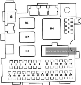
Passenger Compartment Fuse Panel

Fuse Box Location

The fuses are located under the dashboard on the driver’s side


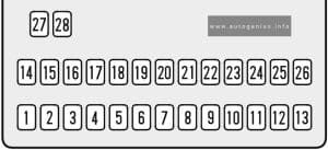
Fuse Box Diagram

Honda HR-V - fuse and relay box diagram - passenger compratment
Honda HR-V – fuse and relay box diagram – passenger compratment


Assignment of the fuses in the instrument panel 

Amps Component(s) or Circuit(s) Protected
1 10A SRS unit (VA)
2 15A SRS unit (VA)
Inertia switch (KG and KE models), PGM-FI main relay (Except KG and KE models)
3 20A Windshield wiper motor, windshield washer motor
4 10A Headlight adjuster switch (KG and KE models), headlight adjuster unit (KG and KE models), rear window intermittent wiper control unit (KG and KE models), rear window washer motor, rear window wiper motor, power window master switch, power window relay
5 10A Integrated control unit, turn signal/hazard relay, back-up lights
6 7.5A Gauge Assembly, Clock, vehicle speed alarm unit (KY model), seat belt alarm unit (KY and KQ models), keyless door lock control unit, secondary HO2S (KG, KE, KN and KQ models), ELD unit (CVT), alternator, VSS, primary HO2S (KG, KE and KU models), PCM, EVAP purge control solenoid valve (KG, KY, KE and KU models)
7 15A Distributor
8 Not used
9 Not used
10 15A Rear window defogger
11 7.5A Blower motor relay, radiator fan relay, condenser fan relay, A/C switch, A/C compressor clutch relay, recirculation control motor, A/C thermostat, ABS modulator assembly, power mirror actuator, power mirror defogger (KG model), power mirror retract actuator (with keyless entry system), seat heater main relay (KG model)
12 Not used
13 7.5A ECM/PCM, PGM-FI main relay
14 Not used
15 Not used
16 Not used
17 Not used
18 15A Audio unit, cigarette lighter
19 Not used
20 Not used
21 Not used
22 Not used
23 7.5A Clock, seat belt alarm unit (KY and KQ models), intregated control unit, ceiling lights, immobiliser indicator light (KG, KE, KQ and KU models), cargo area light, ECM/PCM
24 15A Audio unit
25 15A Keyless / power door lock control unit
26 Not used
27 Not used
28 Not used
S Spare fuses
R1 Power window relay
R2 Taillight relay
R3 Seat heater main relay (KG model)
Shift lock relay (KQ and KU models with CVT)
R4 Turn signal/hazard relay

Engine Compartment Fuse Box

Fuse Box Location

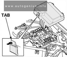
The fuse box is located near the battery.


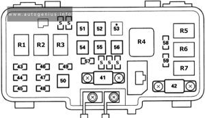
Fuse Box Diagram

Honda HR-V - fuse and relay box diagram - engine compartment
Honda HR-V – fuse and relay box diagram – engine compartment


Assignment of the fuses in the engine compartment

Amps Component(s) or Circuit(s) Protected
41 80A Battery, power distribution
42 50A Ignition switch (BAT)
43 20A Right headlight, High beam indicator light
44 7.5A Rear fog light control unit (KG, KE models)
45 20A Left headlight
46 7.5A / 10A Taillight relay, clock, switch lights, taillights, licence plate lights, integrated control unit, gauge lights, audio unit light, beverage holder light, heater control panel light, front parking lights, dashlights brightness controller (KQ model), option connector C
47 10A / 15A Brake lights, key interlock solenoid (KQ, KU models), ABS modulator assembly ECM/PCM
48 20A ABS modulator assembly
49 10A / 15A Turn signal/hazard lights, hazard warning light (KG and KE models)
50 40A ABS modulator assembly
51 20A Power window relay, passenger’s window motor
52 20A Power window master switch, driver’s window motor
53 Not used
54 30A № 23, 24 and 25 fuses (in under-dash fuse/relay box), option connector B
55 20A Seat heaters (KG model)
56 40A Blower motor
57 20A Radiator fan motor
58 20A Condenser fan motor
A/C compressor clutch
59 15A PGM-FI main relay, data link connector
S Spare fuses
R1 Headlight relay 1
R2 Headlight relay 2
R3 Horn relay
R4 Blower motor relay
R5 Condenser fan relay
R6 Radiator fan relay
R7 A/C compressor clutch relay

WARNING: Terminal and harness assignments for individual connectors will vary depending on vehicle equipment level, model, and market.
Honda Accord Hybrid (2018 – 2019) – fuse and relay box diagram

Honda Accord Hybrid (2018 – 2019) – fuse and relay box diagram

Year of production: 2018, 2019


The Honda Accord Hybrid (2018-2019) is a midsize sedan that blends the Accord’s well-known comfort, practicality, and refinement with hybrid efficiency. This generation introduced an advanced hybrid system aimed at providing impressive fuel economy without sacrificing performance. The Accord Hybrid was a part of the 10th-generation Accord lineup, which featured a more sophisticated design, modern technology, and a spacious, high-quality interior.


Passenger compartment fuse box

Fuse box location

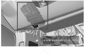
Located under the dashboard.

Honda Accord Hybrid - fuse and relay location - passenger compartment
Honda Accord Hybrid – fuse and relay location – passenger compartment


Fuse box diagram


Assignment of the fuses in the Passenger compartment (2018, 2019)

Circuit Protected Amp
1
2 Driver’s Side Door Unlock 10 A
3 Passenger’s Side Door Unlock 10 A
4 ACCESSORY 10 A
5 ACC Key Lock 7.5 A
6 SRS 10 A
7
8 IG Hold2 (10 A)
9 SMART 10 A
10
11 Driver’s Side Door Lock 10 A
12 Driver’s Door Lock (10 A)
13 Passenger’s Side Door Lock 10 A
14 IG2_Option 10 A
15 Daytime Running Lights 10 A
16 Accessory Power Socket (Console Compartment) (20 A)
17 Moonroof (20 A)
18
19
20 Shift By Wire ECU (10 A)
21 Driver’s Door Unlock (10 A)
22
23
24 Premium Audio (20 A)
25
26
27
28
29
30
31
32 IG Hold3 (15 A)
33 Driver’s Power Seat Sliding (20 A)
34 Passenger’s Power Seat Sliding (20 A)
35 IG1_Option2 10 A
36 Meter 10 A
37 IG 1 _Option 1 10 A
38 Driver’s Power Seat Reclining (20 A)
39 Passenger’s Power Seat Reclining (20 A)
40 Driver’s Lumbar Support (10 A)
41
42 Front Air Ventilated Seat (20 A)
43 +B_Option 10 A
44 ADS (20 A)
45
46 SRS 10 A
47
48 Head-Up Display (10 A)
49 Door Lock 20 A
50 Front Accessory Power Socket 20 A
51 Rear Passenger’s Side Power Window 20 A
52 Rear Driver’s Side Power Window 20 A
53 Front Passenger’s Power Window 20 A
54 Driver’s Power Window 20 A

Engine Compartment Fuse Box

Fuse box location

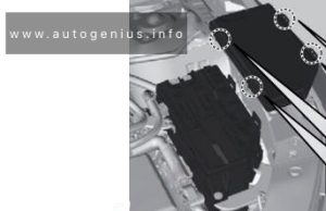
Located near the battery.

Honda Accord Hybrid - fuse and relay location - engine compartment
Honda Accord Hybrid – fuse and relay location – engine compartment


Fuse box diagram


Assignment of the fuses in the Engine compartment (2018, 2019)

Circuit Protected Amp
1 Battery 150 A
2 (70 A)
2 EPS 70 A
2 (30 A)
2 Fuse Box Main 2 60 A
2 Electric Servo Brake 40 A
2 ABS/VSA FSR 40 A
2 SBW 1 30 A
2 IG Main 1 30 A
3 Rear Defogger 40 A
3 Fuse Box Main 1 60 A
3 (30 A)
3 Heater Motor 40 A
3 (40 A)
3 (30 A)
3 (30 A)
3 (30 A)
4 (30 A)
4 Fuse Box Option 2 (70 A)
4 (40 A)
4 Fuse Box Option 1 60 A
5 RFC 40 A
5 (30 A)
5 SRM2 30 A
5 ABS/VSA Motor 40 A
5 IG Main 2 30 A
5 ENG EWP 30 A
6 SRM1 30 A
7
8 Wiper Motor 30 A
9 Brake Light 10 A
10 EVTC 20 A
11 PCU EWP 15 A
12 RFC Coil 10 A
13 IGP 15 A
14 IG Hold 10 A
15 FI ECU 10 A
16 Battery Sensor 7.5 A
17 DBW 15 A
18 Ignition Coil 15 A
19 Hazard 15 A
20
21 P-ACT ECU 7.5 A
22 Heated Steering Wheel (10 A)
23
24 Audio 15 A
25 Rear Seat Heaters (20 A)
26 Heated Windshield (15 A)
27 Back Up 10 A
28 Horn 10 A
29 Front Fog Lights (10 A)
30 A/C EWP (10 A)
31
32 Washer Motor 15 A
33
34 (10 A)
35 Audio Sub (7.5 A)
36 IGPS (LAF) 7.5 A
37 IG1 E-PARKING 7.5 A
38 IG1 IPU 10 A
39 IG1 TCU 10 A
40 IG1 Fuel Pump 20 A
41 IG1 ABS/VSA 7.5 A
42 IG1 ACG 10 A
43 IG1 RFC 7.5 A
44 IG1 Monitor 7.5 A

WARNING: Terminal and harness assignments for individual connectors will vary depending on vehicle equipment level, model, and market.