Volkswagen EOS (2009 – 2011) – fuse and relay box diagram

Volkswagen EOS (2009 – 2011) – fuse and relay box diagram

Year of production: 2009, 2010, 2011, 2012


The Volkswagen Eos coupé-cabriolet was manufactured from 2006 to 2016. This article provides fuse box diagrams for the Volkswagen Eos models from 2009 to 2011. You will also find details on the location of the fuse panels inside the vehicle and information about the fuse and relay assignments (fuse layout).


Instrument Panel Fuse Box (Fuse Panel -SC-)

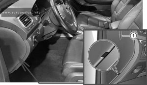
Fuse Box Location

Volkswagen EOS (2006 - 2008) - fuse and relay box location - passenger compartment
Volkswagen EOS (2009 – 2011) – fuse and relay box location – passenger compartment


Fuse Box Diagram

Volkswagen EOS (2006 - 2008) - fuse and relay box diagram - passenger compartment
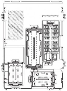
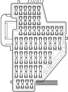
Volkswagen EOS (2009 – 2011) – fuse and relay box diagram – passenger compartment


Assignment of the fuses in the instrument panel

Amps Function/Component
F1 10A 16-Pin Connector – Data Link Connector
Instrument Panel Illumination Dimmer Switch
Mass Air Flow (MAF) Sensor
Auxiliary Heater Operation Relay
Parking Aid Control Module
Headlamp Range/Cornering Lamp Control Module
Positive Crankcase Ventilation (PCV) Heating Element
Left Headlamp Beam Adjustment Motor
Right Headlamp Beam Adjustment Motor
F2 5A Light Switch
Brake Light Switch
ABS Control Module
Electronic Damping Control Module
Motronic Engine Control Module (ECM) Power Supply Relay
Instrument Cluster Control Module
Towing Recognition Control Module
Power Steering Control Module
Data Bus On Board Diagnostic Interface
Fuel Pump (FP) Control Module
Selector Lever Sensors Control Module
Engine Control Module (ECM)
Direct Shift Gearbox (DSG) Mechatronic
F3 10A Airbag Control Module
F4 5A Tire Pressure Monitoring Button
High Pressure Sensor
Oil Level Thermal Sensor
Driver’s Heated Seat Control Module
Front Passenger’s Heated Seat Control Module
Climatronic Control Module
Vehicle Electrical System Control Module 2
Automatic Day/Night Interior Mirror
Left Washer Nozzle Heater
Right Washer Nozzle Heater
F5 Not used
F6 Not used
F7 Not used
F8 Not used
F9 Not used
F10 Not used
F11 Not used
F12 10A Driver’s Door Control Module
Front Passenger’s Door Control Module
F13 10A Light Switch
16-Pin Connector – Data Link Connector
Rain/Light Recognition Sensor
F14 10A Climatronic Control Module
A/C Control Module
Selector Lever Sensors Control Module
Auxiliary Engine Coolant Heating RF Receiver
F15 7.5A Vehicle Electrical System Control Module
F16 Not used
F17 5A Alarm Horn
Radar Interior Monitoring Control Module 1
Radar Interior Monitoring Control Module 2
Vehicle Inclination Sensor –
Alarm Horn Relay (Only applicable to US/CDN)
F18 Not used
F19 7.5A Door Closing Assist Control Module
F20 Not used
F21 Not used
F22 40A Fresh Air Blower Control Module
F23 30A Driver’s Door Control Module
Front Passenger’s Door Control Module
F24 Not used
F25 25A Fresh Air Blower Relay
F26 Not used
F27 15A Fuel Pump (FP) Control Module
Fuel Pump (FP) Relay
Auxiliary Fuel Pump Relay
F28 Not used
F29 Not used
F30 Not used
F31 Not used
F32 30A Left Rear Door Control Module
Right Rear Door Control Module
F33 Not used
F34 15A Driver’s Seat Lumbar Support Adjustment Switch
Front Passenger’s Seat Lumbar Support Adjustment Switch
F35 10A Electronic Damping Control Module
F36 20A Headlamp Washer Relay
Headlamp Washer Pump
F37 30A Front Heated Seats Control Module
F38 20A Comfort System Central Control Module
F39 Not used
F40 40A A/C Control Module
Auxiliary Heater Operation Relay
F41 15A Windshield Washer Pump
F42 15A Blocking Diode 2
Cigarette Lighter
12V Socket
F43 15A Towing Recognition Control Module
F44 20A Towing Recognition Control Module
F45 15A Towing Recognition Control Module
F46 Not used
F47 Not used
F48 Not used
F49 Not used

Relays under instrument panel

Fuse Box Diagram

Volkswagen EOS (2006 - 2008) - fuse and relay box diagram - passenger compartment (relays under instrument panel)
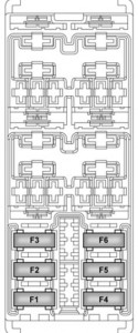
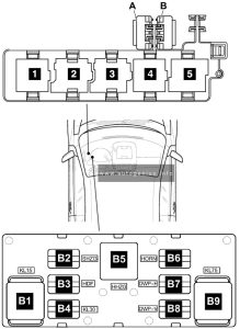
Volkswagen EOS (2009 – 2011) – fuse and relay box diagram – passenger compartment (relays under instrument panel)

Assignment of the raleys in the instrument panel

Amps Function
B1 Power Supply Relay 2 (terminal 15)
B2
B3
B4 Power Supply Relay 2 (terminal 30)
B5 Rear Window Defogger Relay
B6 Dual Horn Relay
B7 Dual Washer Pump Relay 1
B8 Dual Washer Pump Relay 2
B9 Load Reduction Relay
A 20A CB From May 2006 to May 2008: Convertible Top Motor Circuit Breaker
From May 2008: Sunroof Circuit Breaker
B 20A CB Driver’s Power Seat Adjustment Circuit Breaker 1
1 Auxiliary Heater Operation Relay / Alarm Horn Relay (only applicable to US/CDN, from November 2006)
2 Fresh Air Blower Relay (only additional water heater)
3 Power Supply Relay (terminal 50) / Headlamp Washer Relay
4 Headlamp Washer Relay / Fuel Pump (FP) Relay
5 Fuel Pump (FP) Relay / Power Supply Relay (terminal 50)


Engine Compartment Fuse Boxes (Fuse Panels -SA-&-SB-)

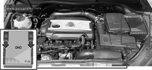
Fuse Box Location

Volkswagen EOS (2006 - 2008) - fuse and relay box location - engine compartment
Volkswagen EOS (2009 – 2011) – fuse and relay box location – engine compartment


Fuse Box Diagram (Version 1, Low)

Volkswagen EOS (2006 - 2008) - fuse and relay box diagram - engine compartment (version 1, low)
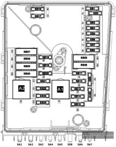
Volkswagen EOS (2009 – 2011) – fuse and relay box diagram – engine compartment (version 1, low)

Assignment of the fuses in the engine compartment (Version 1, Low)

Amps Function/Component
F1 20A From January 2006 to May 2006: Comfort System Central Control Module
F2 5A From January 2006 to May 2008: Steering Column Electronic Systems Control Module
F3 5A Vehicle Electrical System Control Module
F4 20A/30A ABS Control Module
F5 15A Direct Shift Gearbox (DSG) Mechatronic
F6 5A Instrument Cluster Control Module
Steering Column Electronic Systems Control Module (from May 2008)
F7 15A/40A From January 2006 to May 2006: Special Purpose Vehicle Control Module

From May 2008: Power Supply Relay 2 (terminal 15)

F8 15A Radio/Navigation Display Control Module
TV/Radio/Navigation Display/Control Module
Radio
Digital Satellite Radio Tuner
F9 5A Telephone Transceiver
F10 5A/10A Motronic Engine Control Module (ECM) Power Supply Relay (only models with gasoline engine, not for engine code BLF)
Engine Control Module (ECM)
Transmission Control Module (TCM) (From January 2006 to May 2006: )
F11 20A Auxiliary Heater Control Module
F12 5A Data Bus On Board Diagnostic Interface
F13 30A/25A/15A Engine Control Module (ECM)
F14 20A Ignition Coil
Ignition Coil 1-4 with Power Output Stage
F15 10A/5A Heated Oxygen Sensor (HO2S) (BVY)
Oxygen Sensor (O2S) Behind Three Way Catalytic Converter (TWC) (BVY)
Oxygen Sensor (O2S) 2 Behind Three Way Catalytic Converter (TWC) (BVY)
Oxygen Sensor (O2S) 3 Behind Three Way Catalytic Converter (TWC) (BVY)
Fuel Pump (FP) Relay
Automatic Glow Time Control Module
F16 30A ABS Control Module
F17 15A High Tone Horn
Low Tone Horn
F18 30A Special Purpose Vehicle Control Module
Amplifier
F19 30A Wiper Motor Control Module
Windshield Wiper Motor
F20 Not used
F21 10A/15A/25A Oxygen Sensor (O2S) Heater
F22 5A Clutch Position Sensor
F23 5A/10A/15A Secondary Air Injection (AIR) Pump Relay
EGR Vacuum Regulator Solenoid Valve
Wastegate Bypass Regulator Valve
Exhaust Gas Recirculation (EGR) Cooler Switch-Over Valve
Exhaust Gas Recirculation (EGR) Cooler Switch-Over Valve 2
Fuel Pressure Regulator Valve
F24 10A From January 2006 to May 2008:
Map Controlled Engine Cooling Thermostat
Coolant Fan Control (FC) Control Module
EGR Vacuum Regulator Solenoid Valve
Evaporative Emission (EVAP) Canister Purge Regulator Valve 1
Intake Manifold Tuning (IMT) Valve
Camshaft Adjustment Valve 1
Intake Manifold Runner Control (IMRC) Valve
Ignition Coil Power Output StageFrom May 2008: Coolant Fan Control (FC) Control Module
F25 40A From January 2006 to May 2008: Vehicle Electrical System Control Module (T11b/1) Terminal 30 – R
From May 2008: ABS Control Module
F26 40A Vehicle Electrical System Control Module (T11 c/1) Terminal 30 – L
F27 40A/50A Automatic Glow Time Control Module
F28 40A From January 2006 to May 2008: Power Supply Relay 2 (terminal 15)
From May 2008: Convertible Top Control Module
F29 50A From May 2006:
Convertible Top Control Module (From May 2006 to May 2008)
Left Rear Door Control Module
Right Rear Door Control Module
F30 50A Load Reduction Relay
Fuse 7 (on fuse panel C)
Fuse 8 (on fuse panel C)
Fuse 28 (on fuse panel C)
Fuse 35 (on fuse panel C)
SA1 150A/200A Generator (GEN) (90A/120A)
Generator (GEN) (140A)
SA2 80A Power Steering Control Module
Electro-mechanical Power Steering Motor
SA3 50A/80A Coolant Fan Control (FC) Control Module
Coolant Fan
Coolant Fan 2
SA4 40A Special equipment
SA5 80A/100A Fuse 43 (on fuse panel C)
Fuse 45 (on fuse panel C)
Fuse 28 (on fuse panel C)
Fuse 22 (on fuse panel C)
Fuse 18 (on fuse panel C)
Fuse 19 (on fuse panel C)
Fuse 12 (on fuse panel C)
Fuse Panel C
508 Terminal 30 feed
SA6 80A/100A Auxiliary Air Heater Control Module
Auxiliary Air Heater Heating Element
SA7 50A/40A/30A From January 2006 to May 2006:
Trailer
Handicapped equipmentFrom May 2006 to May 2008:
Convertible Top Control Module
Convertible Top Hydraulic Pump
A1 Motronic Engine Control Module (ECM) Power Supply Relay
A2 Secondary Air Injection (AIR) Pump Relay
Connection bridge, Automatic Glow Time Control Module, Glow Plug 1-4

Fuse Box Diagram (Version 2, High)

Volkswagen EOS (2006 - 2008) - fuse and relay box diagram - engine compartment (version 2, high)
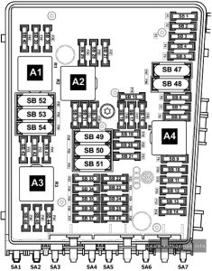
Volkswagen EOS (2009 – 2011) – fuse and relay box diagram – engine compartment (version 2, high)


Assignment of the fuses in the engine compartment (Version 2, High)

Amps Function/Component
F1 30A From January 2006 to May 2006: ABS Control Module
F2 30A ABS Control Module (valves)
F3 20A Comfort System Central Control Module
Transmission Control Module (TCM)
F4 5A Vehicle Electrical System Control Module (measuring cable)
F5 15A Vehicle Electrical System Control Module (horn)
F6 15A Fuel Pressure Regulator Valve
F7 Not used
F8 Not used
F9 10A Turbocharger Recirculating Valve
(BPY, BWA)
Evaporative Emission (EVAP) Canister Purge Regulator Valve 1 (BPY, BWA)
Wastegate Bypass Regulator Valve (BPY, BWA)
F10 Not used
F11 10A Oxygen Sensor (O2S) Heater
F12 10A Oxygen Sensor (O2S) Heater 1 (behind Three Way Catalytic Converter (TWC)
F13 15A Direct Shift Gearbox (DSG) Mechatronic
F14 Not used
F15 10A Coolant Pump
F16 5A From January 2006 to May 2006: ABS Control Module
From May 2006: Steering Column Electronic Systems Control Module
F17 5A Instrument Cluster Control Module
F18 30A Amplifier
F19 15A Radio
Radio/Navigation Display Control Module
F20 5A From January 2006 to May 2006: Radio/Navigation Display Control Module
From May 2006: Telephone Transceiver
F21 Not used
F22 Not used
F23 10A Engine Control Module (ECM)
F24 5A Data Bus On Board Diagnostic Interface
F25 Not used
F26 Not used
F27 Not used
F28 25A Engine Control Module (ECM)
F29 5A Auxiliary Engine Coolant (EC) Pump Relay
F30 20A Auxiliary Heater Control Module
F31 30A Windshield Wiper Motor
F32 Not used
F33 Not used
F34 Not used
F35 Not used
F36 Not used
F37 Not used
F38 10A Coolant Fan Control (FC) Control Module
Camshaft Adjustment Valve 1
F39 5A From January 2006 to May 2006: Brake Pedal Position Sensor
From May 2006: Clutch Position Sensor
F40 20A Ignition Coil 1-4 with Power Output Stage
F41 Not used
F42 5A From January 2006 to May 2006: Engine Component Power Supply Relay
F43 30A From January 2006 to May 2006: Ignition Coil 1-6 with Power Output Stage
F44 Not used
F45 Not used
F46 Not used
F47 40A Vehicle Electrical System Control Module
F48 40A Vehicle Electrical System Control Module
F49 40A Power Supply Relay 2 (terminal 15)
F50 Not used
F51 40A From January 2006 to May 2006: Secondary Air Injection (AIR) Pump Relay
F52 40A Load Reduction Relay
F53 Not used
F54 40A Driver’s Power Seat Adjustment Circuit Breaker 1
Sunroof Circuit Breaker
SA1 150A/200A Generator (GEN) (90A/120A)
Generator (GEN)
SA2 80 A Power Steering Control Module
Electro-mechanical Power Steering Motor
SA3 50A Coolant Fan Control (FC) Control Module
Coolant Fan
Coolant Fan 2
SA4 40A Preheating Coolant, High Heat Output Relay
SA5 80A Fuse 17 (on fuse panel C)
Fuse 16 (on fuse panel C)
Fuse 15 (on fuse panel C)
Fuse 14 (on fuse panel C)
Fuse 13 (on fuse panel C)
Fuse 12 (on fuse panel C)
Fuse Panel C
508 Terminal 30 feed (battery in engine compartment)
SA6 80A Auxiliary Air Heater Control Module
Auxiliary Air Heater Heating Element
SA7 40A Convertible Top Hydraulic Pump
A1 Motronic Engine Control Module (ECM) Power Supply Relay
A2 Auxiliary Engine Coolant (EC) Pump Relay
A3
A4 Engine Component Power Supply Relay


WARNING: Terminal and harness assignments for individual connectors will vary depending on vehicle equipment level, model, and market.

Toyota Land Cruiser 70 (AU 76/78/79; 2009 – 2014) – fuse and relay box diagram

Toyota Land Cruiser 70 (AU 76/78/79; 2009 – 2014) – fuse and relay box diagram

Year of production: 2009, 2010, 2011, 2012, 2013, 2014


This article provides fuse box diagrams for the Toyota Land Cruiser 76/78/79 (Australia) from the years 2009 to 2014. It also includes details on the location of the fuse panels inside the vehicle and explains the function and layout of each fuse.

Passenger Compartment Fuse Box

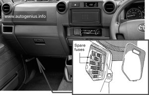
Fuse Box Location

Remove the lid to access.

Toyota Land Cruiser (AU 76/78/79; 2009 - 2014) - fuse box - location passenger compartment
Toyota Land Cruiser (AU 76/78/79; 2009 – 2014) – fuse and relay box – location passenger compartment


Fuse Box Diagrams

Fuse Box №1
Toyota Land Cruiser (AU 76/78/79; 2009 - 2014) - fuse box diagram - passenger compartment
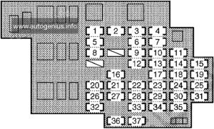
Toyota Land Cruiser (AU 76/78/79; 2009 – 2014) – fuse and relay box diagram – passenger compartment


Assignment of the fuses under the instrument panel

Name Amp Description
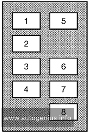
1 DIFF 30A Differential lock system
2 DOOR 30A Power door lock system / wireless remote control system
3 POWER 30A Power windows
4 TRAILER 30A Trailer lights (tail lights), turn signal lights
5 ECU IG 15A 2009-2012: Electronically controlled fuel injection pump system, charging system, engine glow system, four-wheel drive control system, windshield wipers and washer, power antenna, differential lock system
2012-2014: Electronically controlled fuel injection pump system, charging system, engine glow system, four-wheel drive control system, windshield wipers and washer, power antenna, differential lock system, ABS, wireless remote control system
6 WIP 20A Windshield wipers and washer
7 CIG 15A Cigarette lighter
8 GAUGE 15A Back-up lights, air conditioning system, rear window defogger, electronically controlled fuel injection pump system, clock, emergency flashers
9 FUEL HTR 15A Fuel heater
10 ACC 7.5A Clock, audio system, power antenna
11 STOP 15A Electronically controlled fuel injection pump system, stop lights, high mounted stoplight
12 DC/DC 15A DC/DC converter
13 H/LP HI LH 10A No circuit
14 TRAILER STOP 15A Trailer lights (tail lights)
15 PANEL 10A Clock, audio system, emergency flashers, instrument panel light control, door lock system, rear window defogger, power antenna, gauges and meters, air conditioning system
16 DOME №1 10A 2009-2012: Gauges and meters, interior light
2012-2014: Gauges and meters, interior light, wireless remote control system
17 H/LP HI RH 10A Right-hand headlight (high beam), service reminder indicators and warning buzzers
18 OBD2 7.5A On-board diagnosis system
19 TAIL 10A Parking lights, tail lights, license plate lights, electronically controlled fuel injection pump system, trailer lights (tail lights)
20 FR FOG 15A Front fog lights, gauges and meters
21 ECU-B 10A Electronically controlled fuel injection pump system, clock, power antenna
22 INJ 10A Electronically controlled fuel injection pump system
23 H/LP LO LH 10A Left-hand headlight (low beam)
24 STOP 30A All components in “STOP” and “TRAILER STOP” fuses
25 DOME №2 10A Interior lights
26 RR FOG 15A No circuit
27 RADIO 15A Audio system
28 IGN 10A Electronically controlled fuel injection pump system, SRS airbag system
29 H/LP LO RH 10A Right-hand headlight (low beam)
30 DEFOG 20A Electronically controlled fuel injection pump system, rear window defogger
31 EFI №2 10A Electronically controlled fuel injection pump system
32 A/C 10A Air conditioning system
33 MET 10A Gauges and meters
34 ST 7.5A Electronically controlled fuel injection pump system, starting system, engine glow system
35 BLACK 7.5A No circuit
36 SPARE 10A Spare fuse
37 SPARE 20A Spare fuse


Engine Compartment Fuse Boxes

Fuse Box Location

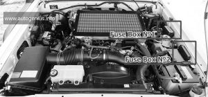
Toyota Land Cruiser (AU 76/78/79; 2009 - 2014) - fuse box location - engine compartment
Toyota Land Cruiser (AU 76/78/79; 2009 – 2014) – fuse and relay box location – engine compartment


Fuse Box Diagrams

Fuse Box №1
Toyota Land Cruiser (AU 76/78/79; 2009 - 2014) - fuse box diagram - engine compartment fuse box no. 1
Toyota Land Cruiser (AU 76/78/79; 2009 – 2014) – fuse and relay box diagram – engine compartment fuse box no. 1


Assignment of the fuses in the Fuse Box №1

Name Amp Description
1 HTR 50A Air conditioning system
2 ALT 140A All components in “GLOW1”, “GLOW2”, “HEAD”, “MAIN1 ”, “MAIN2”, “AM2”, “HORN”, “EFI MAIN”, “EFI MAIN2”, “TURN&HAZ”, “ALT-S”, “H/LP LO RH”, “H/LP LO LH”, “TRAILER”, “H/LP HI RH”, “TAIL”, “PANEL”, “FR FOG”, “DOME”, “ECU-B”, “RADIO” and “DOOR” fuses
3 GLOW1 80A Engine glow system
4 GLOW2 80A Engine glow system
5 AM1 №2 50A 2009-2012: All components in “ECU IG”, “GAUGE” and “WIP” fuses
2012-2014: All components in “ECU IG”, “GAUGE” and “WIP” fuses, front fog lights, rear fog lights
6 AM1 30A Cigarette lighter, starting system, all components in “ST” and “ACC” fuses
7 AM1 №3 50A Cigarette lighter, all components in “ACC” fuse
8 ALT MAIN 50A Stop lights, air conditioning system, on-board diagnosis system, audio system
Fuse Box №2
Toyota Land Cruiser (AU 76/78/79; 2009 - 2014) - fuse box diagram - engine compartment fuse box no. 2
Toyota Land Cruiser (AU 76/78/79; 2009 – 2014) – fuse and relay box diagram – engine compartment fuse box no. 2


Assignment of the fuses in the Fuse Box №2

Name Amp Description
1 HEAD 50A Right-hand headlight (low beam), left-hand headlight (low beam), right-hand headlight (high beam), left-hand headlight (high beam)
2 MAIN2 50A 2009-2012: Audio system, all components in “ECU-B”, “DOME №1”, “DOME №2” and “DOOR” fuses
ABS MTR 50A 2012-2014: ABS
3 MAIN1 50A 2009-2012: Tail lights, front fog lights, rear fog lights, all components in “PANEL” fuse
2012-2014: Tail lights, all components in “PANEL” fuse, trailer, audio system, all components in “ECU-B”, “DOME №1” and “DOOR” fuses
4 AM2 50A All components in “MET”, “IGN” and “INJ” fuses
5 HORN 10A Horns
6 EFI MAIN 15A Electronically controlled fuel injection pump system
7 EFI MAIN2 15A Electronically controlled fuel injection pump system
8 TURN&HAZ 15A Turn signal lights, tail lights, service reminder indicators and warning buzzers, trailer lights (tail lights)
9 ABS SOL 30A 2012-2014: ABS
10 ALT-S 7.5A Charging system

WARNING: Terminal and harness assignments for individual connectors will vary depending on vehicle equipment level, model, and market.
Holden Acadia (2018 – 2020) – fuse and relay box diagram

Holden Acadia (2018 – 2020) – fuse and relay box diagram

Year of production: 2018, 2019, 2020


The Holden Acadia (AC), a mid-size crossover SUV, was manufactured between 2018 and 2020. This article provides fuse box diagrams for the 2018, 2019, and 2020 Holden Acadia models, details the locations of the fuse panels within the vehicle, and explains the function and layout of each fuse and relay.


Passenger Compartment Fuse Box

Fuse Box Location

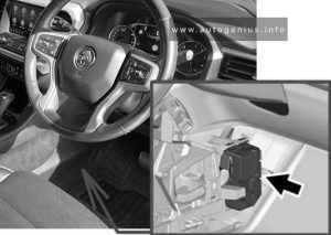
The instrument panel fuse block is inside the centre console on the right-hand side of the vehicle.

Holden Acadia (2018 - 2020) - fuse and relay box location - passenger compartment
Holden Acadia (2018 – 2020) – fuse and relay box location – passenger compartment


Fuse Box Diagram

Holden Acadia (2018 - 2020) - fuse and relay box diagram - passenger compartment
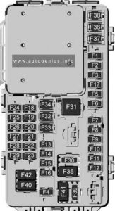
Holden Acadia (2018 – 2020) – fuse and relay box diagram – passenger compartment


Assignment of the fuses in passenger compartment

Usage
F1 Body control module 6
F2 Diagnostic link / Central gateway module
F3 Electric steering column lock
F4
F5
F6 Heating, ventilation, and air conditioning
F7 Body control module 3
F8
F9 Right front heated seat
F10 Airbag / Seat belt
F11
F12 Amplifier / Noise control module
F13 Body control module 7
F14 Left front heated seat
F15
F16 Sunroof
F17
F18 Instrument cluster
F19 Body control module 1
F20 Rear seat entertainment
F21 Body control module 4
F22 Infotainment USB data / Aux jack
F23 Body control module 2
F24 USB charger / Wireless charging
F25 Ultrasonic park aid
F26 CIM
F27
F28 Heating, ventilation, and air conditioning display
F29 Radio
F30 Steering wheel adjustment controls
F31 2018-2019: Front blower
2020: Electronic brake control module electric brake booster
F32 DC AC inverter
F33 Driver power seat
F34 Passenger power seat
F35 Battery IEC 1 feed
F36 Electric power steering
F37 Rear seat entertainment / USB charge / Wireless charging module / Auxiliary power outlet
F38 Body control module 8
F39
Circuit Breakers
F40
F41
F42 Auxiliary power outlet / Lighter

Engine Compartment Fuse Box

Fuse Box Location

Holden Acadia (2018 - 2020) - fuse and relay box location - engine compartment
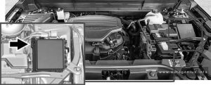
Holden Acadia (2018 – 2020) – fuse and relay box location – engine compartment


Fuse Box Diagram

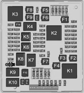
Holden Acadia (2018 - 2020) - fuse and relay box diagram - engine compartment
Holden Acadia (2018 – 2020) – fuse and relay box diagram – engine compartment


Assignment of the fuses in the engine compartment

Usage
F1 Antilock brake system
F2 Starter 1
F3 DC/DC transformer 1
F4
F5 DC/DC transformer 2
F6
F7 2018-2019: Electronic brake control module eboost
2020: Front blower
F8 Starter 3
F9
F10 2020: Brake lamp trailer
F11
F12 Front wiper
F13 2020: Starter 2
F14
F15 Rear wiper
F16
F17
F18
F19
F20
F21
F22 Electronic brake control module
F23 Parking / Trailer lamps
F24 Right trailer stop lamp / lndicator lamp
F25 Steering column lock
F26
F27 Left trailer stop lamp / Indicator lamp
F28
F29
F30 Washer pump
F31 Spare / Headlamp low-beam right
F32 Headlamp low-beam left
F33 Headlamp hi-beam shutter / Fog lamps
F34 Horn
F35
F36 Headlamp low-beam right / Headlamp high-beam left
F37 Spare / Headlamp high-beam right
F38 Automatic headlamp levelling motor
F39 Transmission control module
F40 Left rear bus electrical centre / Ignition
F41 Instrument cluster
F42 Heating, ventilation, and air conditioning / Central gateway module run/crank
F43 Reflective light alert display
F44 Electronic brake control module eboost run/crank
F45
F46
F47
F48
F49 Interior rear view mirror / Trailer
F50 Fuel system control module / Fuel tank zone module run / crank
F51 Heated steering wheel
F52 Air conditioning clutch
F53
F54 Coolant pump
F55
F56
F57 Engine control module / lgnition
F58 Transmission control module / lgnition
F59 Engine control module battery
F60
F61 O2 sensor 1 / Aero shutter / Mass air flow sensor
F62 Engine control module – odd
F63 O2 sensor 2
F64 Engine control module – even
F65 Engine control module powertrain 1
F66 Engine control module powertrain 2
F67 Engine control module powertrain 3
F68
F69
F70
F71
F72
F73
F74
F75
F76
F77
Relays
K1 Starter 1
K2 Run/Crank
K3 Starter 3
K4
K5
K6 Coolant pump
K7 Engine control module
K8 Air conditioning
K9 2020: Brake trailer lamp
K10 2020: Starter 2

Rear Compartment Fuse Box

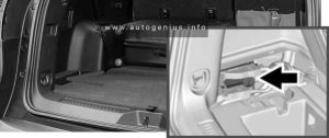
Fuse Box Location

The rear fuse panel is located below the left-hand side trim panel in the rear compartment.

Holden Acadia (2018 - 2020) - fuse and relay box location - rear compartment
Holden Acadia (2018 – 2020) – fuse and relay box location – rear compartment


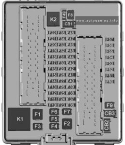
Fuse Box Diagram

Holden Acadia (2018 - 2020) - fuse and relay box diagram - rear compartment
Holden Acadia (2018 – 2020) – fuse and relay box diagram – rear compartment


Assignment of the fuses in the rear compartment

Usage
F1
F2 Trailer battery
F3
F4 Rear blower
F5 Rear drive control 1
F6
F7 Right window
F8 Rear demister
F9 Left window
F10
F11 Trailer reverse
F12
F13
F14
F15
F16
F17
F18
F19
F20 Glove box door / Trailer brake lamp
F21
F22
F23
F24
F25
F26 Trailer brake
F27 Driver ventilated seat / Lumbar
F28 Passive entry / Passive start
F29
F30 Canister vent
F31
F32 Heated mirror
F33
F34 Liftgate module
F35 Fuel system control module / Fuel tank zone module
F36 Passenger ventilated seat / Lumbar
F37
F38 Window module
F39 Rear closure
F40 Memory seat module
F41 Automatic occupancy sensor
F42
F43
F44
F45 Liftgate motor
F46 Rear heated seats
F47
F48
F49
F50
F51
F52 Rear drive control 2 / Active dampening system module
F53 Video
F54 External object calculating / Side blind zone alert
F55
F56 Universal garage door opener / Rain sensor
F57 Theft deterrent
Circuit Breakers
CB1
CB2
CB3 Rear auxiliary power outlet
Relays
K1
K2


WARNING: Terminal and harness assignments for individual connectors will vary depending on vehicle equipment level, model, and market.
Alfa Romeo MiTo (2008 – 2013) – fuse box diagram

Alfa Romeo MiTo (2008 – 2013) – fuse box diagram

Year of production: 2008, 2009, 2010, 2011, 2012, 2013

The Alfa Romeo MiTo (Series 955) was first introduced in 2008 and underwent a restyling in 2014. Although there were no significant external changes, a new trim for the headlight surround and a chrome grille were added. Internal changes varied depending on the configuration and year of manufacture. This article focuses on the fuse and relay boxes of the Alfa Romeo MiTo from 2009 to 2018, providing diagrams and locations.

Engine compartment fuse box

Fuse box location

Located next to the battery. 

Alfa Romeo MiTo (2008 - 2012) - fuse box location - engine compartment
Alfa Romeo MiTo (2008 – 2012) – fuse box location – engine compartment


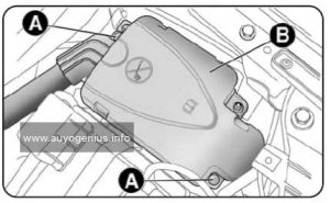
To access, unscrew screws A and remove cover B.

Alfa Romeo MiTo (2009 - 2012) - fuse box location - engine compartment
Alfa Romeo MiTo (2008 – 2012) – fuse box location – engine compartment

Fuse box diagram

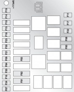
Alfa Romeo MiTo - fuse box - engine compartment
Alfa Romeo MiTo – fuse box – engine compartment
Alfa Romeo MiTo (2008 - 2012) - fuse box diagram - engine compartment
Alfa Romeo MiTo (2008 – 2012) – fuse box diagram – engine compartment

Dashboard fuse box

Fuse box location

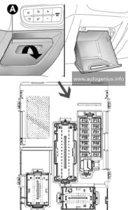
It is located under the dashboard on the left. To access it, you need to open the protective cover.

Alfa Romeo MiTo (2008 - 2012) - fuse box location - passenger compartment
Alfa Romeo MiTo (2008 – 2012) – fuse box location – passenger compartment


Fuse box diagram

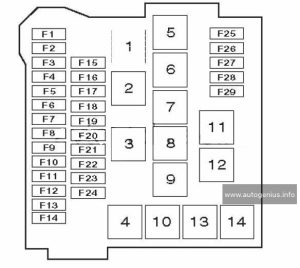
Alfa Romeo MiTo - fuse box - dashboard
Alfa Romeo MiTo – fuse box – dashboard


Luggage compartment fuse box

Fuse box diagram

Alfa Romeo MiTo - fuse box - luggage
Alfa Romeo MiTo – fuse box – luggage

Fuse summary table

Lights Fuse Ampere rating [A] Location
Main beams F14 15 Engine compartment
Right hand dipped beam headlight F12 7,5 Dashboard
Left hand dipped beam headlight F13 7,5 Dashboard
Headlight gas discharge system (right side) F12 15 Dashboard
Headlight gas discharge system (left side) F13 15 Dashboard
Fog lights F30 15 Engine compartment
3rd Brake light F37 5 Dashboard
Reversing light F51 5 Dashboard
Front courtesy light, luggage compartment light, Sun visor courtesy light, Door lights, Glove compartment light F32 5 Dashboard


Consumers Fuse Ampere rating [A] Location
Passenger compartment fan F08 30 Engine compartment
Headlight washer pump F09 20 Engine compartment
Two-tone horn F10 15 Engine compartment
Waste gate solenoid, Shut off solenoid, Canister solenoid, Lambda Sensor Heater, VGT solenoid, EGR cooling bypass solenoid, Swirl solenoid, Throttle solenoid, Glow plug preheating control unit F11 10 Engine compartment
Headlight alignment adjustment system f13 7,5 Dashboard
Additional heater (PTC 1) F15 30 Engine compartment
Engine management control unit F16 5 Engine compartment
Engine management control unit (power supply) F17 10 Engine compartment
Control system relay coil, Engine management control unit (1.4 versions), Engine cooling system remote control switch coil (300W+300W) F18 5 Engine compartment
Air conditioning compressor F19 7,5 Engine compartment
Heated rear windscreen, demisting system F20 30 Engine compartment
Fuel pump on tank F21 15 Engine compartment
Engine management system main loads (1.4 versions) F22 10 Engine compartment
Engine management system main loads (1.6 JTDM versions) F22 20 Engine compartment
Braking system control unit (control unit and solenoid unit) F23 20 Engine compartment
Electric steering control unit (power supply + Key), Brake system control unit (power supply + Key), Yaw sensor on tunnel F24 5 Engine compartment
INT/A key exhaust relay coils on engine fuse box F31 5 Dashboard
Radio, Blue&MeTM control unit, Climate control unit, Alarm control unit, Volume sensing system control unit, EOBD external diagnostic socket, Tyre pressure detection control unit F36 10 Dashboard
Instrument panel, Brake light switch, Gas discharge headlights management system F37 5 Dashboard
Door lock motor on door, Safe Lock motor on doors, Tailgate unlocking motor F38 15 Dashboard
Windscreen / rearscreen washer pump F43 20 Dashboard
Electric window motor complete with control unit (driver-side door) F47 20 Dashboard
Electric window motor complete with control unit (passenger-side door) F48 20 Dashboard
Parking sensors control unit, Tyre pressure detection control unit, Rain/dusk sensor on rear-view mirror, Electro-chrome sensor on rear-view mirror, Seat belts fastened warning light display on rear-view mirror, Control panel illumination (Central control panel, Driver-side control panel, Steering wheel control panel, Blue&MeTM control panel), Front seat heating pad activation switch, Alarm system volume-sensing sensors control unit, Electric sunroof control unit, PND socket on dashboard F49 5 Dashboard
Air Bag system control unit F50 7,5 Dashboard
Clutch switch, Brake light switch, relay coils on engine fuse box, Control system on internal heater/air conditioning unit, Blue&MeTM control unit, Radio wiring, Air flow meter, Water in diesel fuel sensor F51 5 Dashboard
Instrument panel F53 5 Dashboard
Bose HI-FI system amplifier control unit F4 15 Luggage
Bassbox subwoofer in spare wheel compartment F5 10 Luggage
Left and right front seat heater F6 15 Luggage
Electric sunroof opening system F1 20 Luggage
Fuse wiring F2 Luggage
Luggage compartment power socket F3 15 Luggage
Passenger compartment fan F83 40 Engine compartment
Power socket on tunnel F85 15 Engine compartment
Passenger/driver-side door mirror demister, Demister on front jets, Heated windscreen relay coil F87 7,5 Engine compartment

WARNING: Terminal and harness assignments for individual connectors will vary depending on vehicle equipment level, model, and market.
Fiat Croma 2nd generation (Tipo 194) (2005 – 2009) – specification

Fiat Croma 2nd generation (Tipo 194) – specification

Year of production: 2005, 2006, 2007, 2008, 2009

Identification data

Production/sales period of cars with this particular specs early-year 2007 – late-year 2009
Country of origin Italy, Turin
Manufacturer Fiat
Model Croma 2nd generation (Tipo 194)
Segmentation D1 (large sedans)
Class mid-size/large family car
Body style hatchback/station wagon crossover
Doors 5
Traction FWD (front – wheel drive)

Dimensions and capacities

Length 4783 mm (188.3 in)
Width 1775 mm (69.9 in)
Height 1603 mm (63.1 in)
Wheelbase 2700 mm (106.3 in)
Front trak 1524 mm (60 in)
Rear track 1524 mm (60 in)
Trunk (cargo) capacity VDA 500/893/1610 dm3 (17.7/31.5/56.9 cu ft)

Weights

Curb weight 1430 kg/3153 lbs
Gross vehicle weight right GVWR 1950 kg/4299 lbs
Payload 520 kg/1146 lbs
Towing weight
unbraked 700 kg/1543 lbs
braked 1500 kg/3307 lbs

Emission standard: Euro 4

BUICK Enclave – vehicle specification

BUICK Enclave – vehicle specification


Capacities and Specifications

Application Capacities
English Metric
Air Conditioning Refrigerant R134a For the air conditioning system refrigerant charge amount, see the refrigerant caution label located under the hood.
Cooling System 11.4 qt 10.8 L
Engine Oil with Filter 5.5 qt 5.2 L
Fuel Tank 22.0 gal 83.3 L
Transmission Fluid 5.3 qt 5.0 L
Wheel Nut Torque 140 lb ft 190 N*m

Engine Specifications

Engine VIN Vode Transmission Spark Plug Gap
3.6L V6 Engine D Automatic 0.043 in (1.10 mm)


WARNING: Terminal and harness assignments for individual connectors will vary depending on vehicle equipment level, model, and market.
BMW Z8 E52 – vehicle specification

BMW Z8 E52 – vehicle specification


Engine specification

BMW Z8
Displacemen cu in (ccm) 301.5 (4,941)
Number of cylinders 8
Maximum output at engine speed hp 394
rpm 6,600
Maximum torque at engine speed ft lbs (Nm) 368 (500)
rpm 3,800
Compression ratio E 11
Stroke in (mm) 3.50 (89.0)
Bore in (mm) 3.70 (94.0)
Fuel injection system Digital electronic engine-management system


Dimensions

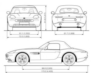
BMW Z8 E52 - dimensions
BMW Z8 E52 – dimensions

Weights

BMW Z8
Curb weight (with one person, ready for operation, full tank of fuel, without hardtop) Ibs. (kg) 3,725 (1,690)
Approved gross vehicle weight Ibs. (kg) 4,255 (1,930)
Approved front axle weights Ibs. (kg) 2,028 (920)
Approved rear axle weights Ibs. (kg) 2,359 (1,070)
Approved roof load capacity Ibs. (kg)
Luggage compartment capacity cu ft (litres) 7.2 (203)

WARNING: Terminal and harness assignments for individual connectors will vary depending on vehicle equipment level, model, and market.
BMW Z8 – fuse box location

BMW Z8 – fuse box location


In glove compartment

  1. Open the glove compartment
  2. Unlock the fuse box and swing it downward
  3. Remove the lid with the list on it. Spare fuses and plastic tweezers are located in the fuse box lid behind the passenger-side seat


Behind the passenger’s seat

  1. Move the passenger’s seat forward and open the storage compartment located behind it. The list is on the lid’s inside cover.
  2. Remove the fuse box lid containing the spare fuses and the plastic tweezers


WARNING: Terminal and harness assignments for individual connectors will vary depending on vehicle equipment level, model, and market.
BMW Z4 sDrive35is (2011) – specifications

BMW Z4 sDrive35is (2011) – specifications

Engine specification

Displacement cu in/cm3 181.8/2,976
No. of cylinders 6
Maximum output hp 335
at engine speed rpm 5,900
Maximum torque lb ft/Nm 335/454
at engine speed rpm 1,500

Dimensions

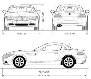
BMW Z4 sDriver35is - dimensions
BMW Z4 sDriver35is – dimensions

Wights

Approved gross vehicle weight
Manual transmission lbs/kg
With authomatic transmission lbs/kg 4,178/1,895
Load lbs/kg 562/255
Approved front axle load lbs/kg 1,918/870
Approved rear axle load lbs/kg 2,271/1,030
Trunk capacity cu ft/l 6.4 – 10.9/180 -310

WARNING: Terminal and harness assignments for individual connectors will vary depending on vehicle equipment level, model, and market.
BMW Z4 sDrive35i (2011) – specifications

BMW Z4 sDrive35i (2011) – specifications

Engine specification

Displacement cu in/cm3 181.8/2,976
No. of cylinders 6
Maximum output hp 300
at engine speed rpm 5,800
Maximum torque lb ft/Nm 300/407
at engine speed rpm 1,400 – 5,000

Dimensions

BMW-Z4-sDriver30i-sDriver35i-dimensions
BMW Z4 sDriver35i – dimensions

Wights

Approved gross vehicle weight
Manual transmission lbs/kg 4,134/1,875
With authomatic transmission lbs/kg 4,178/1,895
Load lbs/kg 562/255
Approved front axle load lbs/kg 1,918/870
Approved rear axle load lbs/kg 2,271/1,030
Trunk capacity cu ft/l 6.4 – 10.9/180 -310

WARNING: Terminal and harness assignments for individual connectors will vary depending on vehicle equipment level, model, and market.