Nio EL8 (2020 – 2023) – fuse and relay box diagram
Year of production: 2020, 2021, 2022, 2023
This article provides fuse box diagrams for the Nio EL8 / Nio ES8 models from 2020 to 2023. You will also discover the location of the fuse panels within the vehicle and find details about the fuse and relay assignments (fuse layout).
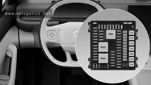
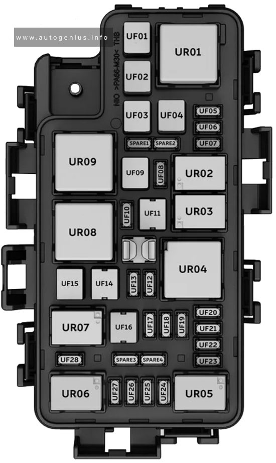
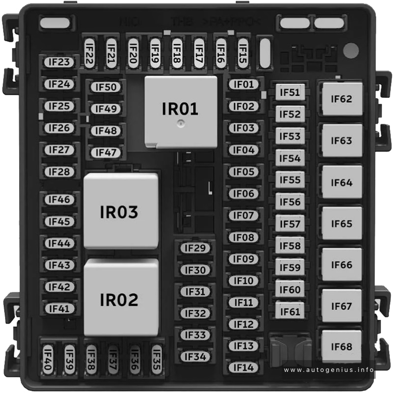
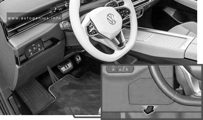
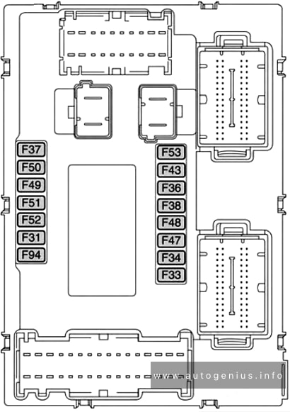
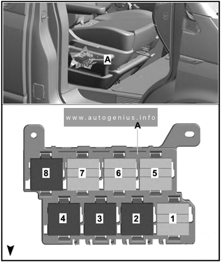
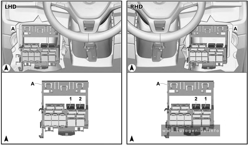
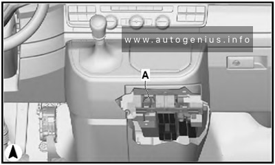
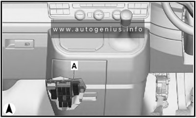
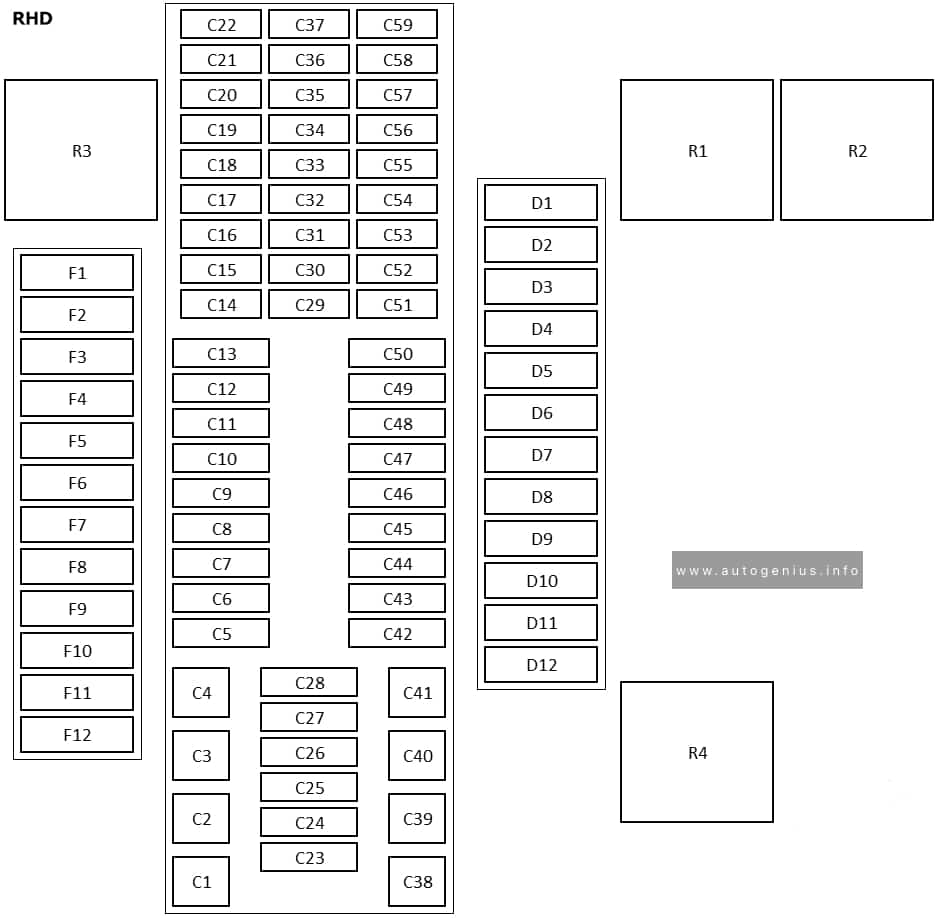
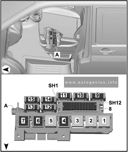
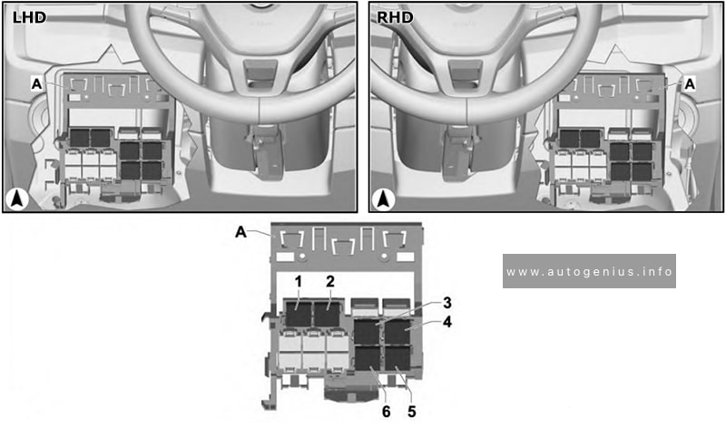
Passenger Compartment Fuse Box
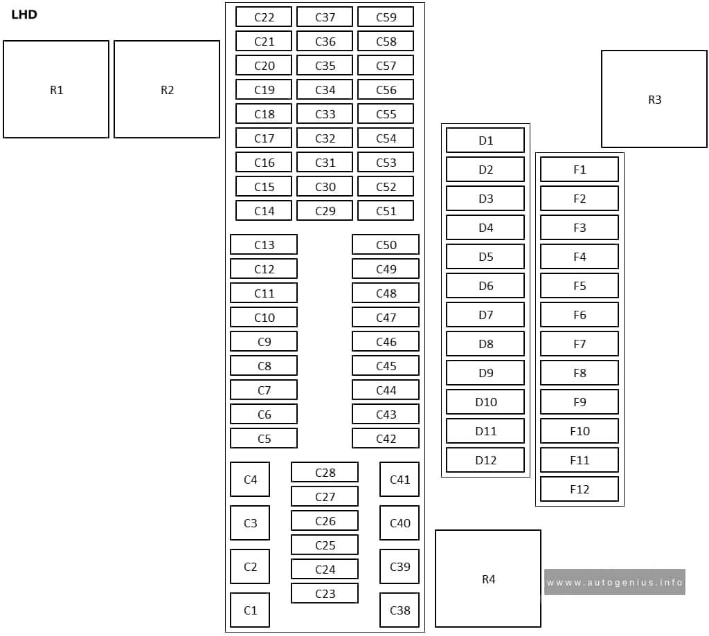
Fuse box diagram
Assignment of the fuses in the dashboard
| № | Amps | Description |
|---|---|---|
| 1 | IF02 / IF29 / IF26 fuse (KL15 power supply) relay | |
| 2 | (Reserved) relay | |
| 3 | TR03 relay power supply / TR06 relay coil / IF01 / IF25 / IF27 / IF30 / IF43 / TF01 / TF25 fuse (KL15 power supply) relay | |
| 4 | (Reserved) | |
| 5 | (Reserved) | |
| 6 | 10A | Brake booster / electric power steering-1 (KL15 power supply) fuse |
| 7 | 15A | Driver seat heating / ventilation / lumbar support / massage module (KL15 power supply) fuse |
| 8 | 10A | KL15-Trailer |
| 9 | 10A | Electric parking controller / electric power steering-2 (KL15 power supply) fuse |
| 10 | 10A | IR04 relay (coil) / right front headlight / rear-view mirror assembly / left front headlight (KL15 power supply) fuse |
| 11 | 15A | Passenger side heating / ventilation/lumbar support / massage module (KL15 power supply) fuse |
| 12 | 10A | Airbag controller (KL15 power supply) fuse |
| 13 | 10A | Radar / parking radar controller / central gateway controller (KL15 power supply) fuse |
| 14 | 15A | Steering wheel heating (KL15 power supply) fuse |
| 15 | 10A | Climate control module / front body controller / central gatewaycontroller / vehicle controller / ECALL / DAB box / DAB adaptor (KL15 power supply) / side mirrormemory feedback + fuse |
| 16 | (Reserved) | |
| 17 | (Reserved) | |
| 18 | 30A | Electric parking controller 1 (KL30 power supply) |
| 19 | (Reserved) | |
| 20 | 25A | IR02 relay power supply fuse |
| 21 | (Reserved) | |
| 22 | 25A | Front body controller (front wipers) KL30 power supply fuse |
| 23 | 40A | Sunroof / sunshade motor (KL30 power supply) fuse |
| 24 | IF28 fuse (KL15 power supply) relay | |
| 25 | (Reserved) | |
| 26 | 30A | Front body control module 1 fuse |
| 27 | 30A | Front body control module 2 fuse |
| 28 | 10A | Digital instrument cluster / HUD / NOMI / eCall (KL30 power supply) fuse |
| 29 | 10A | Climate control module / rear climate control panel and fragrance system (KL30 power supply) fuse |
| 30 | 10A | Body control module (safe box lock power supply) /DAB box fuse |
| 31 | 10A | Steering column power supply fuse |
| 32 | 10A | Brake switch (KL30 power supply) fuse |
| 33 | 10A | Driver’s side door control switch / rain sensor / wireless charging power supply (models with air suspension) fuse |
| 34 | 20A | Infotainment system console (KL30 power supply) 1 fuse |
| 35 | 10A | Body controller (KL30 power supply) fuse |
| 36 | 30A | IR04 relay switch power supply fuse |
| 37 | (Reserved) | |
| 38 | (Reserved) | |
| 39 | 60A | Brake booster fuse |
| 40 | 30A | Electric parking controller 2 (KL30 power supply) |
| 41 | Left side mirror left adjustment relay | |
| 42 | 10A | Climate control module (KL30 power supply) fuse |
| 43 | 20A | Battery management unit (KL30 power supply) fuse |
| 44 | 10A | Center display (KL30 power supply) fuse |
| 45 | 10A | Electronic gear selector module (KL30 power supply) fuse |
| 46 | 30A | Front body control module (central lock) fuse |
| 47 | 10A | IR06 / IR08 / IR09 relay fuse |
| 48 | 10A | ADAS main controller (KL30 power supply) fuse |
| 49 | 10A | Diagnosis interface (KL30 power supply) fuse |
| 50 | 10A | IR10 / IR11 / IR12 relay fuse |
| 51 | 10A | IR07 / IR13 relay fuse |
| 52 | 15A | IR05 power supply fuse |
| 53 | 10A | Central gateway controller (KL30 power supply) fuse |
| 54 | Side mirror unfold relay | |
| 55 | (Reserved) | |
| 56 | Left side mirror right/upward adjustment relay | |
| 57 | Left side mirror downward adjustment relay | |
| 58 | Right side mirror left adjustment relay | |
| 59 | Right side mirror right/upward adjustment relay | |
| 60 | Right side mirror downward adjustment relay | |
| 61 | Side mirror fold relay |
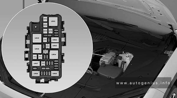
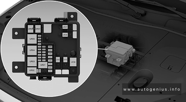
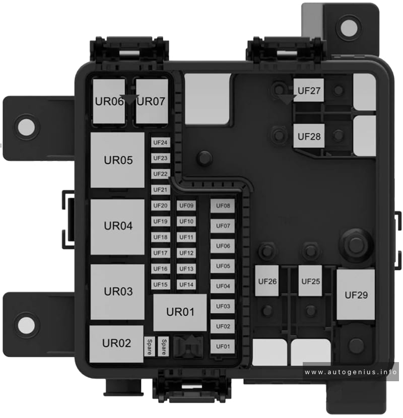
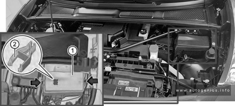
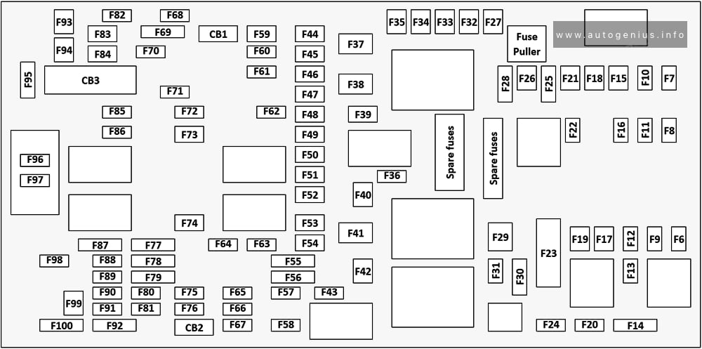
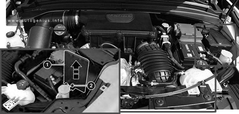
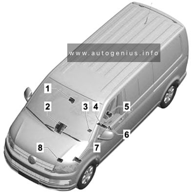
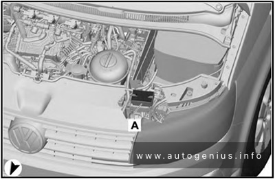
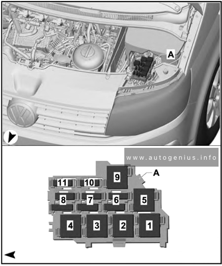
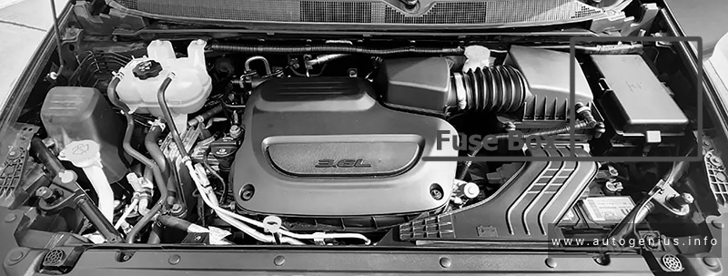
Engine Compartment Fuse Box
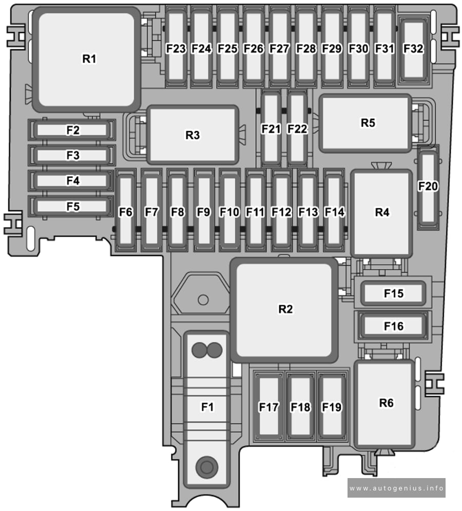
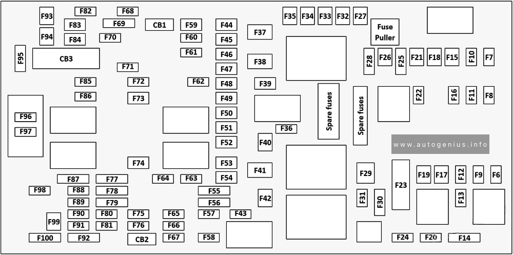
Fuse Box Diagram
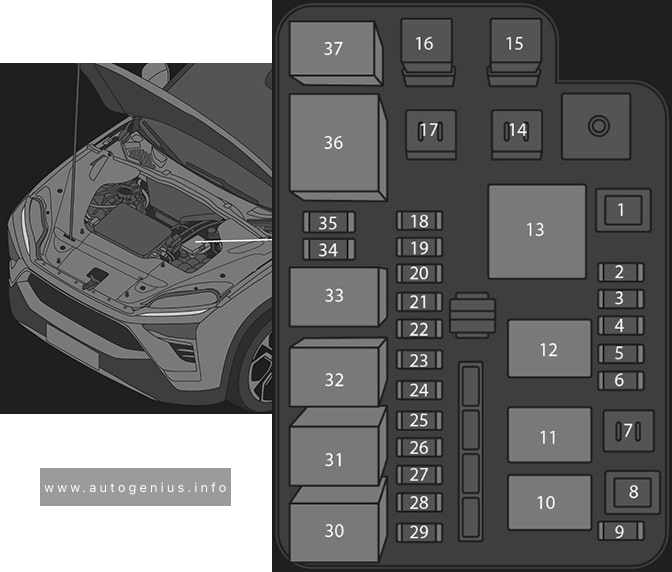
Assignment of the fuses in the engine compartment fuse box
| № | Amps | Description |
|---|---|---|
| 1 | 60A | UR06 relay power supply fuse |
| 2 | 10A | High voltage integrated component |
| 3 | 20A | Washer pump fuse |
| 4 | 15A | UR05 relay power supply fuse |
| 5 | 10A | Vehicle communication controller / high voltage charging indicator fuse |
| 6 | 15A | UR04 relay power supply fuse |
| 7 | (Reserved) | |
| 8 | (Reserved) | |
| 9 | 15A | UR07 relay power supply fuse |
| 10 | Front motor cooling water pump relay | |
| 11 | Rear motor cooling water pump relay | |
| 12 | Battery cooling water pump relay | |
| 13 | Cooling fan relay | |
| 14 | (Reserved) | |
| 15 | 40A | Brake control module (control unit) fuse |
| 16 | 40A | Brake control module (motor) fuse |
| 17 | (Reserved) | |
| 18 | 15A | Vehicle controller (KL87) fuse |
| 19 | 10A | Climate control system fuse |
| 20 | 10A | UR04 coil / UR05 coil / UR06 coil / UR07 coil / fan / brake switch / active grille shutter / high voltage battery pack heating / three-way valve / four-way valve fuse |
| 21 | 10A | Left high beam fuse |
| 22 | 10A | Right high beam fuse |
| 23 | 10A | ADAS main controller power supply 2 fuse |
| 24 | 15A | UR08 relay power supply fuse |
| 25 | 10A | Left low beam fuse |
| 26 | 20A | Battery management system power supply fuse |
| 27 | 15A | Front power control unit fuse |
| 28 | 10A | Central gateway controller power supply 2 fuse |
| 29 | 10A | Right low beam fuse |
| 30 | Right low beam relay | |
| 31 | Left low beam relay | |
| 32 | Horn relay | |
| 33 | High beam relay | |
| 34 | 10A | High voltage power distribution box / gear shifter module fuse |
| 35 | (Reserved) | |
| 36 | Main relay | |
| 37 | (Reserved) |
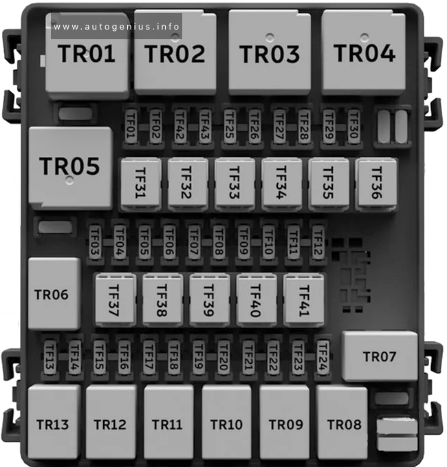
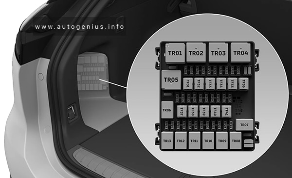
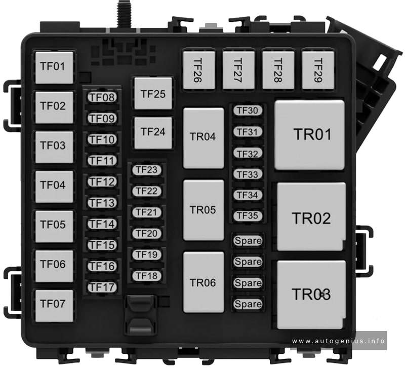
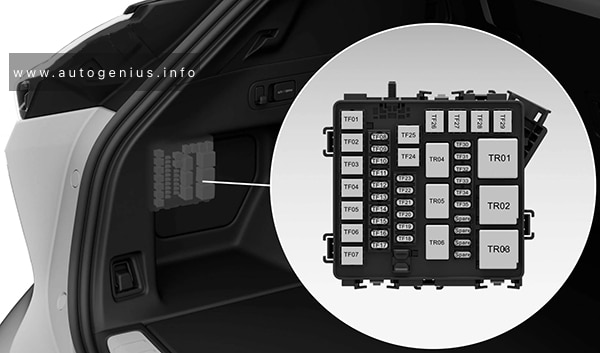
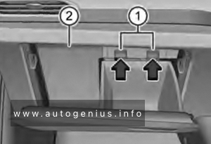
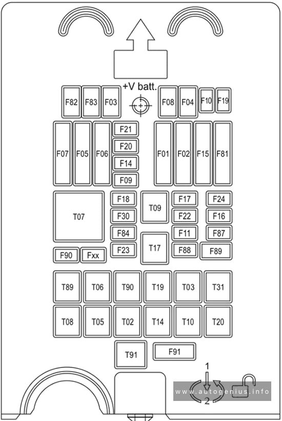
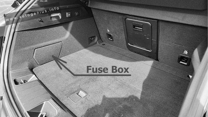
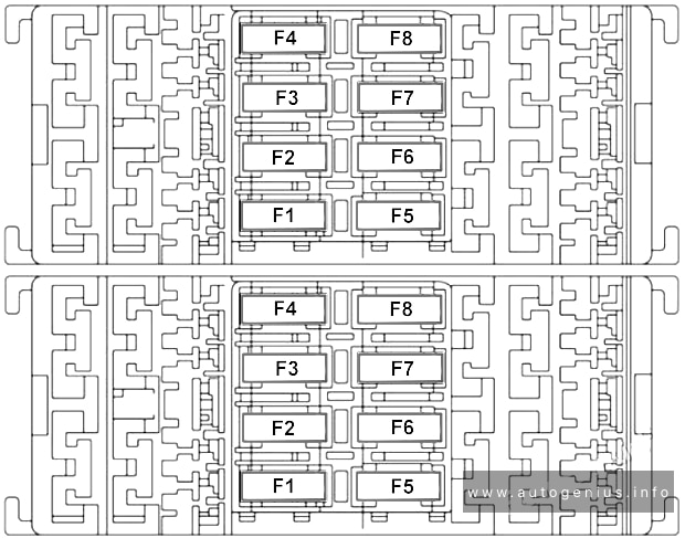
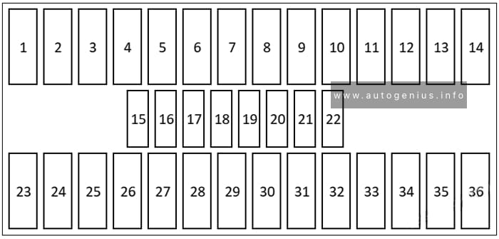
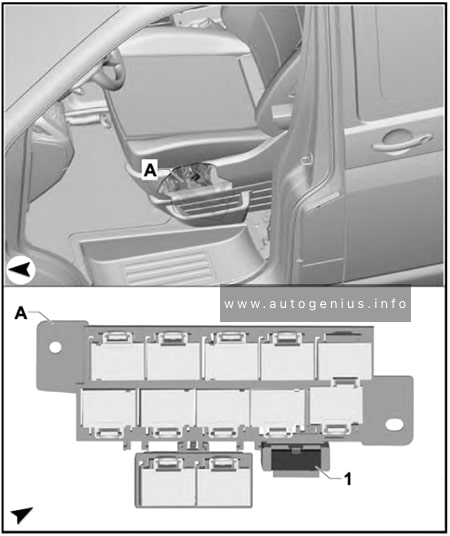
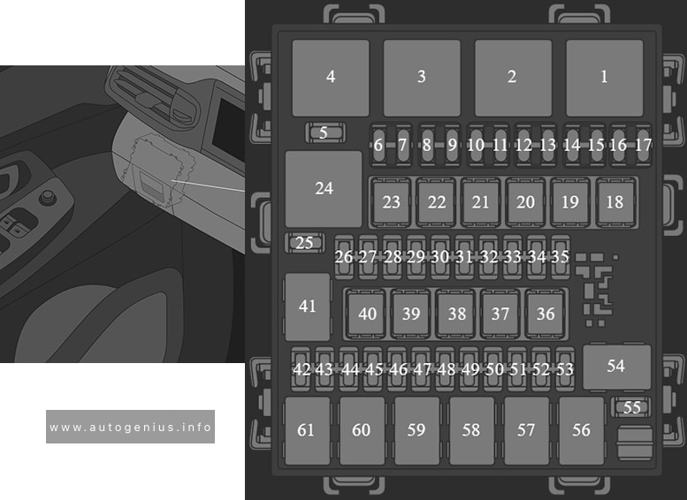
Luggage Compartment Fuse Box
Fuse Box Diagram
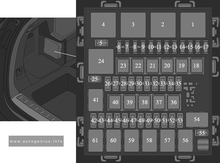
Assignment of the fuses in the luggage compartment
| № | Amps | Description |
|---|---|---|
| 1 | TF02/TF27 fuse power supply relay | |
| 2 | KL15 power supply | |
| 3 | Rear blower (KL30 power supply) relay | |
| 4 | Front blower (KL30 power supply) relay | |
| 5 | (Reserved) | |
| 6 | 10A | Wheel arch light / ambient lighting / safe box limit switch fuse |
| 7 | 15A | Left front and rear exterior door handle deploy + / retract – fuse |
| 8 | 15A | Left front and rear exterior door handle deploy – / retract + fuse |
| 9 | 15A | Right front and rear exterior door handle deploy – / retract + fuse |
| 10 | 10A | Liftgate taillight / body taillight / sunroof switch / vanity mirror light / puddle light fuse |
| 11 | 10A | USB hub (KL15 power supply) fuse |
| 12 | 15A | Right front and rear exterior door handle deploy + /retract – fuse |
| 13 | 10A | Right side mirror heating fuse |
| 14 | 10A | Left side mirror heating fuse |
| 15 | 10A | Second row seat USB fuse |
| 16 | (Reserved) | |
| 17 | (Reserved) | |
| 18 | 25A | Left front / right rear window regulator motor (KL30 power supply) fuse |
| 19 | 60A | TR01 relay contactor power supply fuse |
| 20 | 30A | Passenger seat adjustment fuse |
| 21 | 30A | Driver seat adjustment fuse |
| 22 | 40A | Air suspension controller (air pump) KL30 power supply fuse |
| 23 | 30A | Liftgate control module (motor) fuse |
| 24 | TF42/TF43 fuse power supply | |
| 25 | (Reserved) | |
| 26 | 20A | Air suspension controller (KL30 power supply) fuse |
| 27 | 15A | CC2 charge port motor power supply fuse |
| 28 | 15A | TR07 relay power supply fuse |
| 29 | 10A | Rear inverter (KL30 power supply) fuse |
| 30 | 10A | Liftgate control module fuse |
| 31 | 20A | Infotainment system console (KL30 power supply) 2 fuse |
| 32 | 30A | TR04 relay switch power supply fuse |
| 33 | 30A | TR05 relay switch power supply fuse |
| 34 | 30A | Rear body controller power supply 1 fuse |
| 35 | 10A | Kick sensor / TR04 coil / TR05 coil / TR08 coil / TR09 coil / TR11 coil fuse |
| 36 | 30A | Amplifier control unit fuse |
| 37 | 25A | TR03 relay power supply fuse |
| 38 | 40A | TR11 relay contactor power supply fuse |
| 39 | 30A | TR02 relay contactor power supply fuse |
| 40 | 25A | Right-front / left-rear window regulator motor (KL30) fuse |
| 41 | Second row seat heating relay | |
| 42 | 10A | Vehicle controller power supply fuse |
| 43 | 15A | Rear wiper fuse |
| 44 | 15A | TR10 relay / TR12 relay fuse |
| 45 | 30A | Rear body controller power supply 2 fuse |
| 46 | 25A | TR06 relay contactor power supply fuse |
| 47 | 25A | TR08 relay contactor power supply fuse |
| 48 | 25A | TR09 relay contactor power supply fuse |
| 49 | (Reserved) | |
| 50 | 10A | TR13 relay fuse |
| 51 | 20A | Trailer control module power1 |
| 52 | 20A | Trailer control module power2 |
| 53 | (Reserved) | |
| 54 | TF29 / TF28 fuse power supply | |
| 55 | (Reserved) | |
| 56 | TF26 fuse / TF30 fuse / front 12V power socket power supply | |
| 57 | Rear 12V power socket | |
| 58 | Second row left seat easy entry relay | |
| 59 | Rear defogger relay | |
| 60 | Second row right seat easy entry relay | |
| 61 | Liftgate lock relay |
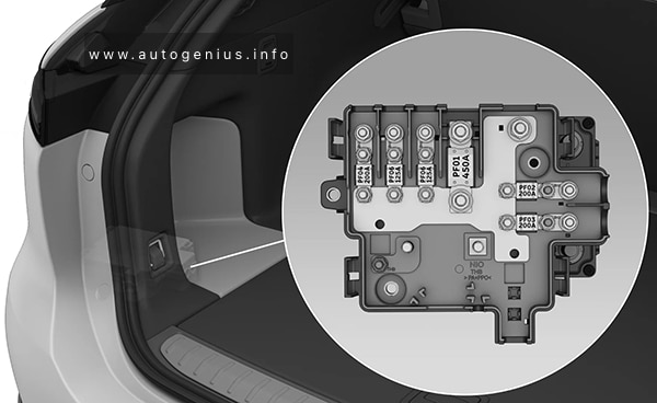
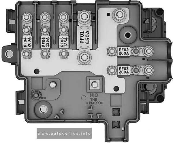
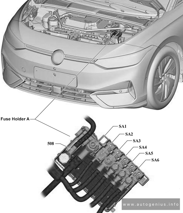
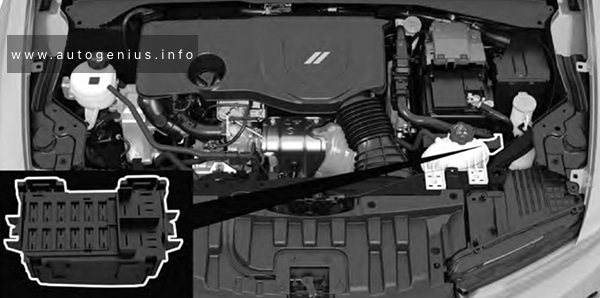
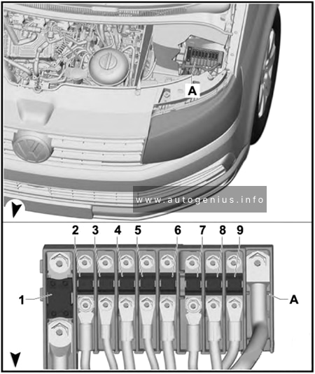
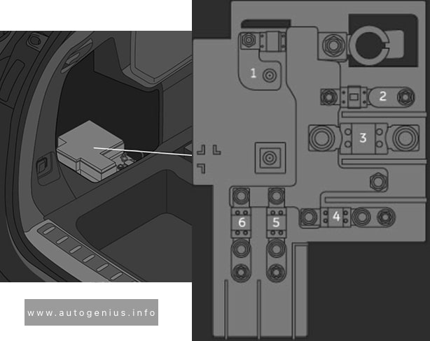
Pre-Fuse Box
Fuse Box Diagram
| № | Amps | Description |
|---|---|---|
| 1 | 30A | Pyrotechnic safety switch power supply |
| 2 | 125A | Electric power steering gear power supply |
| 3 | 300A | DC/DC converter power supply |
| 4 | 200A | Trunk fuse box power supply |
| 5 | 125A | Instrument panel electrical box power supply |
| 6 | 125A | Underhood electrical box power supply |
WARNING: Terminal and harness assignments for individual connectors will vary depending on vehicle equipment level, model, and market.