Holden Colorado (RG; 2017 – 2020) – fuse box diagram
Year of production: 2017, 2018, 2019, 2020
This article provides the second-generation Holden Colorado (RG, facelifted) produced from 2017 to 2020. It includes fuse box diagrams for the 2017, 2018, 2019, and 2020 models, provides details on the location of the fuse panels within the vehicle, and explains the function of each fuse (fuse layout).
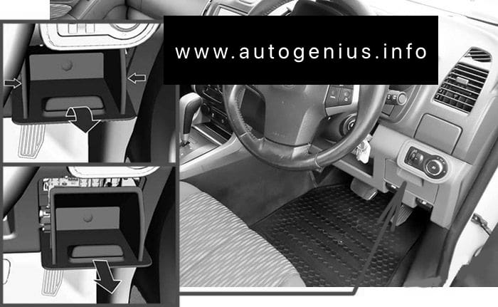
Passenger Compartment Fuse Box
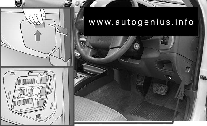
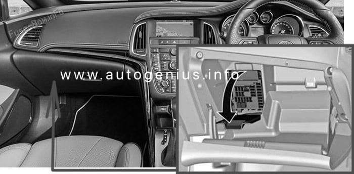
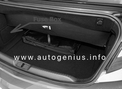
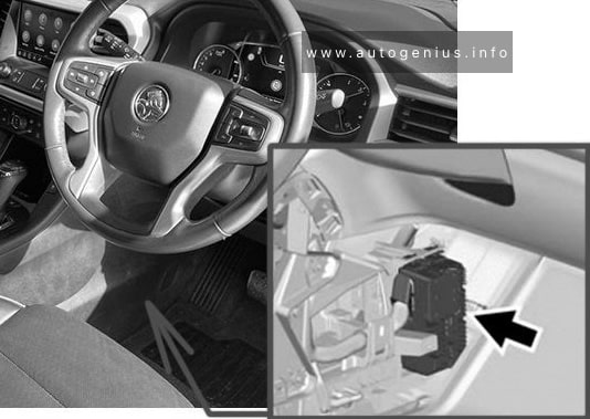
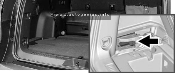
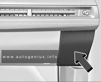
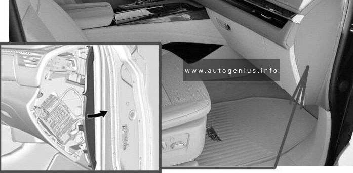
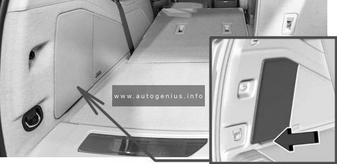
Fuse Box Location
The fuse box is in a storage compartment on the driver’s side of the instrument panel. Remove the instrument panel cap in the direction of the arrow to access.
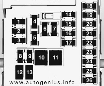
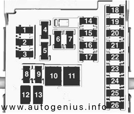
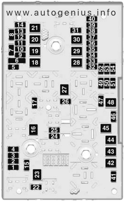
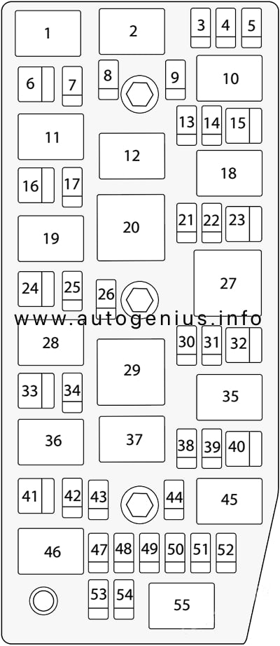
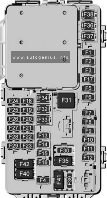
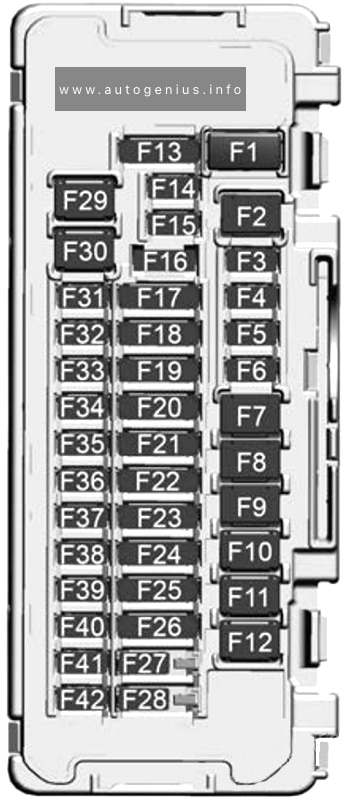
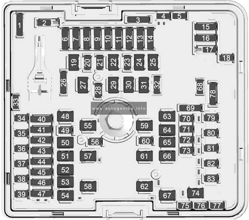
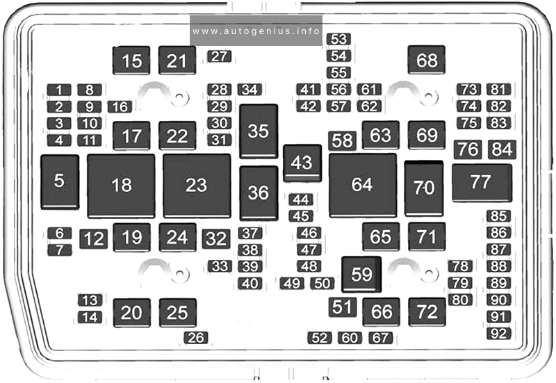
Fuse Box Diagram
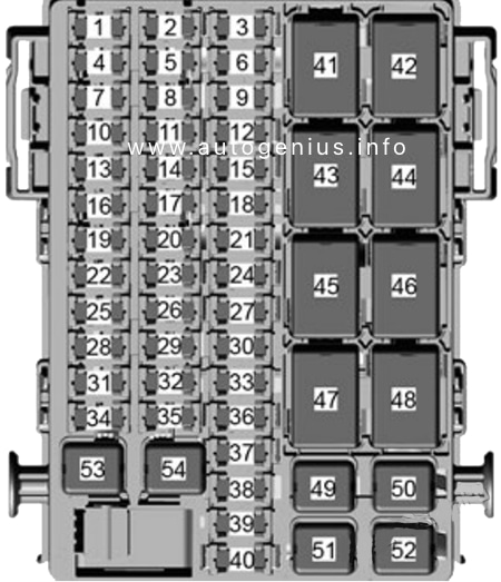
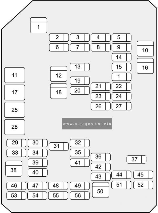
Assignment of the fuses in the passenger compartment (instrument panel)
| № | Amps | Usage |
|---|---|---|
| 1 | 20A | Body Control Module (6) |
| 3 | 20A | Cigarette Lighter (if available) |
| 6 | 20A | Front and Rear Power Outlets (if available) |
| 7 | 30A | Body Control Module (8) |
| 10 | 20A | Radio (if available) |
| 11 | 2A | Ignition Switch |
| 12 | 15A | Side Blind Zone (SBZ) (If available) |
| 13 | 15A | Body Control Module (3) |
| 14 | 10A | Front A/C Control Module |
| 15 | 15A | Seat Heated (If available) |
| 16 | 15A | Body Control Module (1) |
| 17 | 30A | Front Door Power Window Switch |
| 19 | 30A | Rear Door Power Window Switch (if available) |
| 20 | 15A | Body Control Module (4) |
| 21 | 10A | Spare |
| 22 | 30A | Power Seat (if available) |
| 25 | 10A | Sensing and Diagnose Module (SDM) |
| 26 | 15A | Body Control Module (2) |
| 27 | 2A | Clock Spring |
| 28 | 7.5A | Data Link Connector (DLC) |
| 31 | 10A | Instrument Panel Cluster (IPC), Displays – Radio (Instrument Panel), USB |
| 33 | 10A | Central Gateway Module (CGM) – Cyber Security |
| 34 | 30A | Front A/C Blower |
| 37 | 10A | Front Collision Alert (FCA) / Rain Sensor (if available) |
| 39 | 10A | Rear View Mirrors (if available) |
| 53 | 40A | BUS-C (fuses: F12, F33, F37, F39, F40) |
| 54 | 40A | Accessory (12V) |
| Relays | ||
| RLY45 | C-Enable | |
| RLY46 | RAP and Accessory (12V) | |
| RLY48 | Run relay |
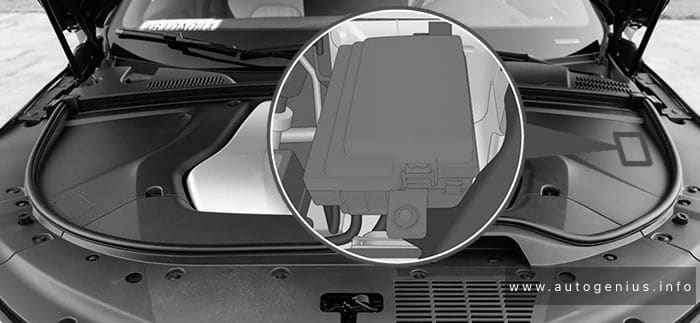
Engine Compartment Fuse Box
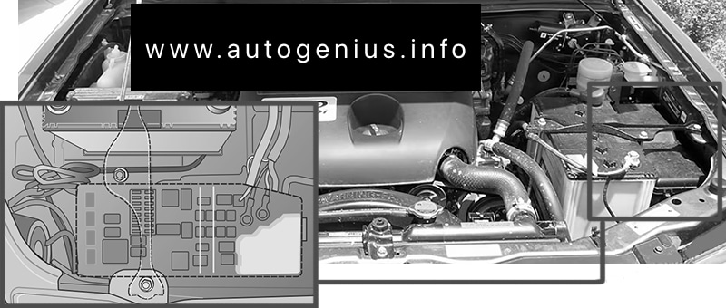
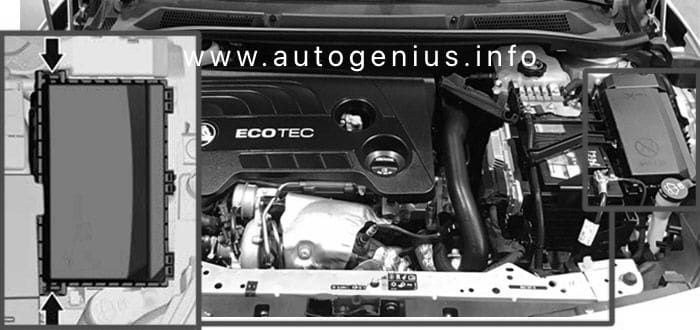
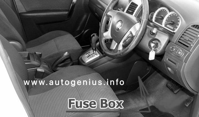
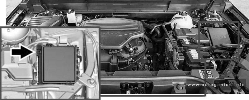
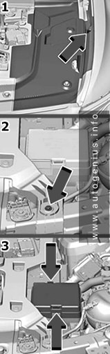
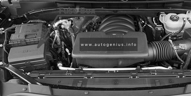
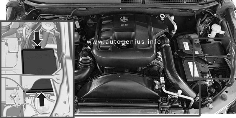
Fuse Box Location
The fuse box is in the front left of the engine compartment. Disengage the cover, lift it upward and remove it.
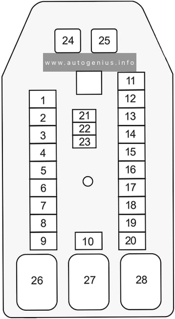
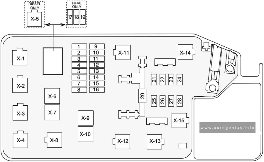
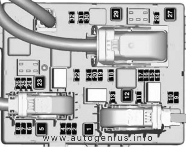
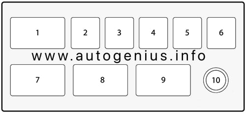
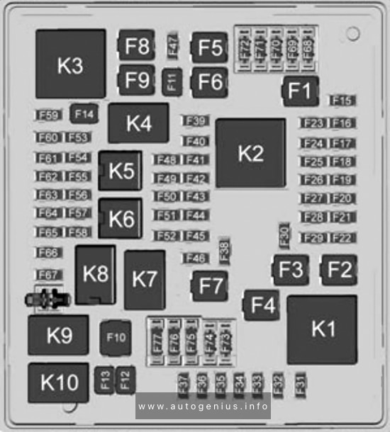
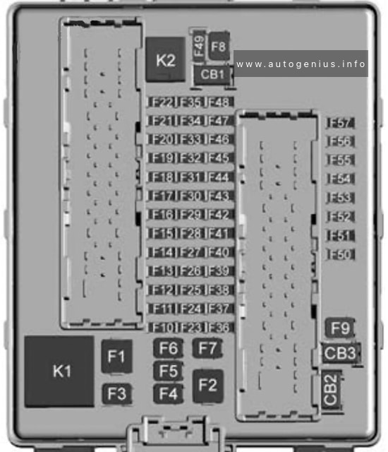
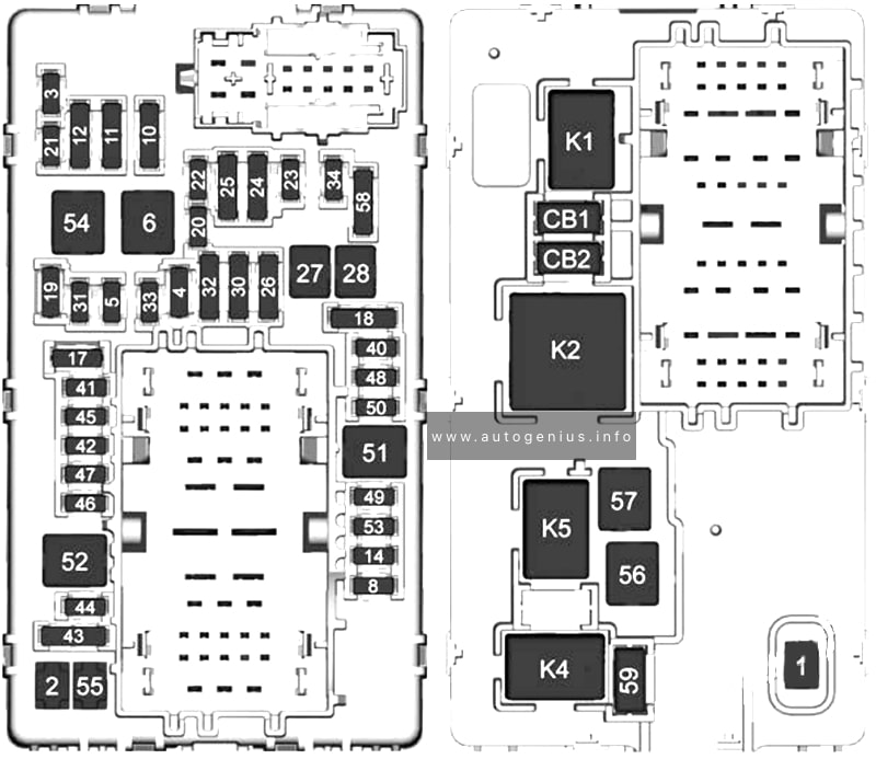
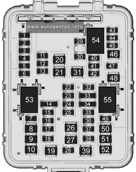
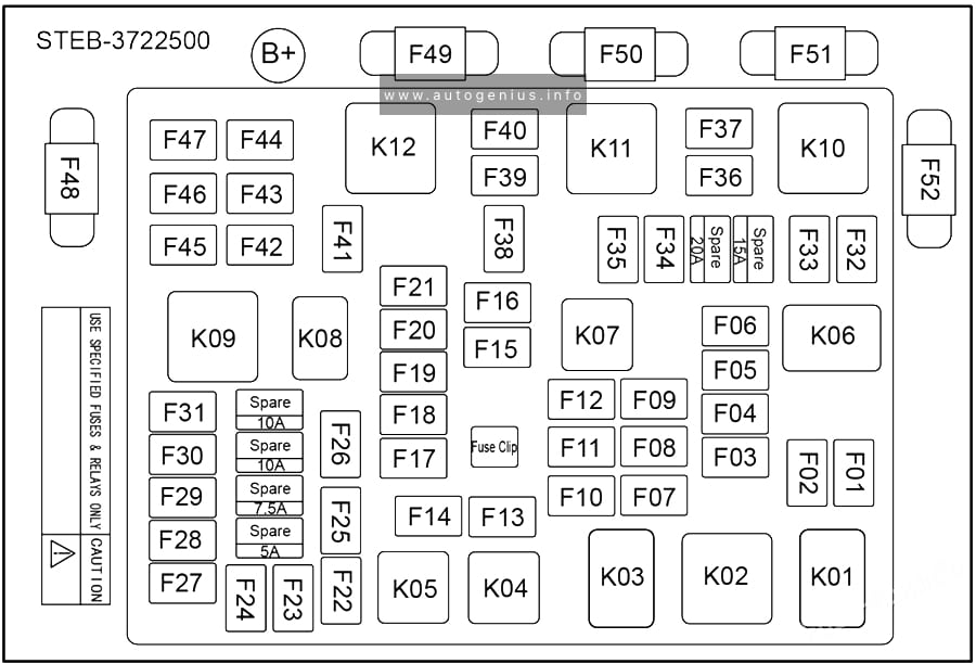
Fuse Box Diagram
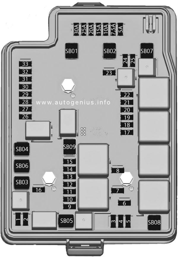
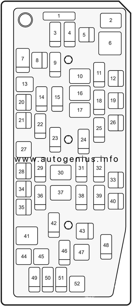
Assignment of the fuses in the engine compartment
| № | Amps | Usage |
|---|---|---|
| 1 | 10A | Compressor A/C Clutch |
| 2 | – | Not Used |
| 3 | 15A | Electric Power Steering (EPS) (if available) |
| 4 | – | Not Used |
| 5 | 15A | Horn |
| 6 | 15A | Front Fog Lamp (if available) |
| 7 | 10A | High Beam LH |
| 8 | 10A | High Beam RH |
| 9 | 7.5A | Engine Control Module – (Diesel) |
| 10 | 15A | Powertrain Relay (3) – (Diesel) |
| 11 | 20A | Engine Control Module (1) (Diesel) |
| 12 | 10A | Powertrain Relay (1) |
| 13 | 10A | Powertrain Relay (2) |
| 14 | 15A | Powertrain Relay (4) |
| 15 | 15A | Run Crank Relay Signal |
| 16 | 15A | Automatic Transmission Control Module (if available) |
| 17 | 10A | Transfer Case Module, Head Lamp Leveling, Trailer Interface Module (if available) |
| 18 | 10A | Power Supply Cluster – A/C – Airbag Module |
| 19 | 20A | Fuel Pump (Diesel) |
| 20 | – | Not Used |
| 21 | 30A | Rear Defogger (if available) |
| 22 | 15A | Outside Rear View Mirror Defogger (if available) |
| 23 | 15A | 2017: Cab Heater (Diesel) |
| 24 | 20A | Rear Wiper (SUV) |
| 25 | 10A | Front / Rear (SUV) Washer Pump |
| 26 | 10A | Park Assist (if available) |
| 27 | 5A | Body Control Module |
| 28 | 15A | Auxiliary Lamps Provision (If equipped) |
| 29 | 30A | ABS or ESC Module (if available) |
| 30 | 10A | Horn |
| 31 | 15A | Body Control Module |
| 32 | 15A | Engine Control Module (Battery) (Diesel) |
| 33 | 10A | Communication Wire Between Modules |
| SB01 | 50A | ABS or ESC Module Pump (if available) |
| SB02 | 30A | Transfer Case Control Module (4X4) (if available) |
| SB03 | 60A | Preheating Glow Plug Module (Diesel) |
| SB04 | – | Not Used |
| SB05 | 30A | Starter Motor Solenoid |
| SB06 | 30A | Front Wiper |
| SB07 | 30A | Fuel Heater (Diesel) |
| SB08 | – | Not Used (Diesel) |
| SB09 | 30A | Spare |
| F34* | 30A | Trailer Hitch Module (if available) * Located near battery positive terminal |
| Relays | ||
| RLY01 | Starter | |
| RLY03 | High Beam | |
| RLY05 | 2017: Viscous Heater (Diesel) | |
| RLY08 | Front Wiper Control | |
| RLY09 | Front Wiper Speed | |
| RLY10 | Rear Defogger and Outside Rear View Mirror Defogger (if available) | |
| RLY11 | Powertrain | |
| RLY12 | A/C Clutch | |
| RLY13 | Fuel Heater (Diesel) | |
| RLY14 | Not Used (Diesel) | |
| RLY15 | Not Used | |
| RLY18 | Run Crank | |
| RLY19 | Fuel Pump (Diesel) |
WARNING: Terminal and harness assignments for individual connectors will vary depending on vehicle equipment level, model, and market.