Volkswagen Golf VIII (MK8; 2020 – 2024) – fuse and relay box diagram
Year of production: 2020, 2021, 2022, 2023, 2024
This article provides the eighth-generation Volkswagen Golf (MK8), produced from 2020 to the present. It provides fuse box diagrams for the Volkswagen Golf VIII models from 2020, 2021, and 2022, along with details on the location of the fuse panels within the vehicle. Additionally, it explains the fuse and relay assignments (fuse layout).
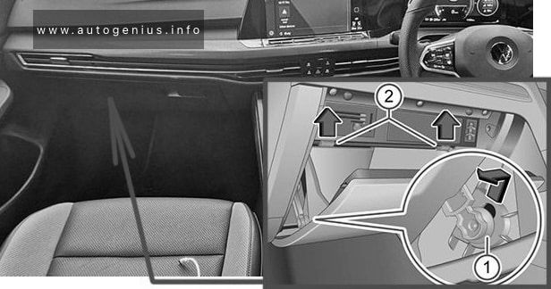
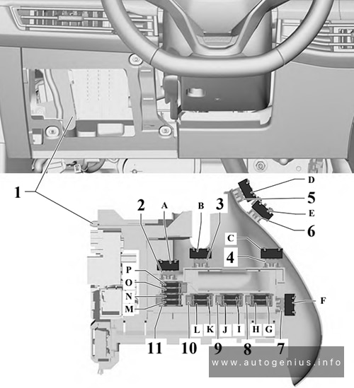
Passenger Compartment Fuse Box (Fuse Panel C -SC-)
Fuse Box Location
Left-hand drive
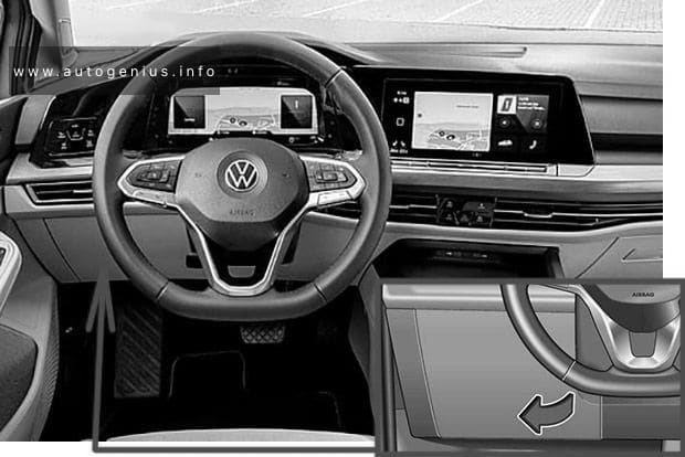
Right-hand drive
Fuse Box Diagram
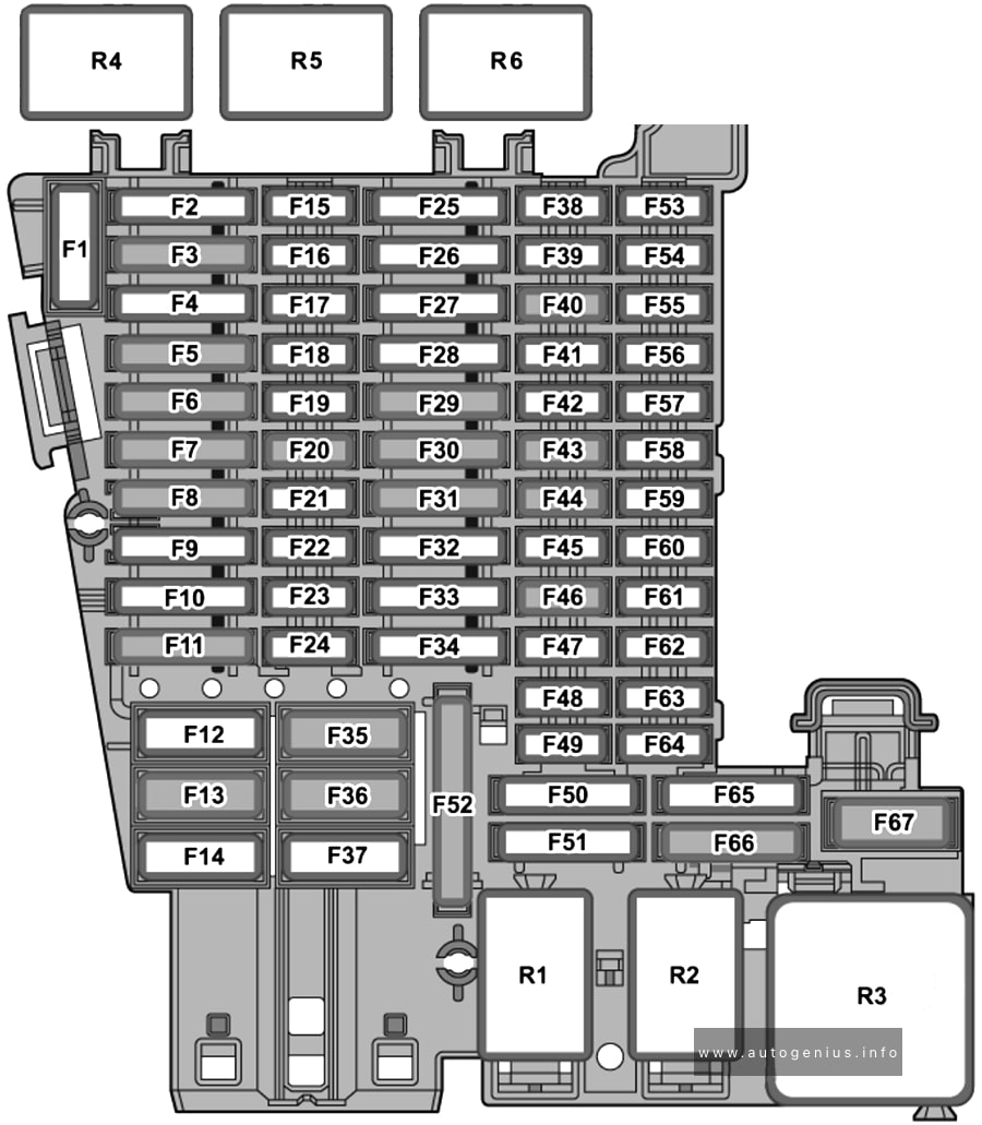
Assignment of the fuses in the passenger compartment (instrument panel)
| № | Amps | Function / component |
|---|---|---|
| SC1 | – | – |
| SC2 | – | – |
| SC3 | 25 A | Trailer detector control unit |
| SC4 | 20 A | Control unit for reducing agent heater (diesel) |
| SC5 | 25 A | Parking lock actuator |
| SC6 | 30 A | Onboard supply control unit Interior lighting |
| SC7 | 30 A | Heater and air conditioning system control unit Seat heating |
| SC8 | 20 A | Sliding sunroof adjustment control unit |
| SC9 | 30 A | Driver door control unit (left-hand drive models) Front passenger door control unit (right-hand drive models) Rear driver side window regulator motor (left-hand drive models) Rear passenger side window regulator motor (right-hand drive models) |
| SC10 | – | – |
| SC11 | 15 A | Trailer detector control unit |
| SC12 | 40 A | Onboard supply control unit Exterior lighting (left-side) |
| SC13 | 40 A | Onboard supply control unit Central locking |
| SC14 | 30 A | Digital sound package control unit |
| SC15 | – | – |
| SC16 | 7.5 A | Airbag control unit |
| SC17 | 10 A | Relay for reducing agent metering system |
| SC18 | 7.5 A | Interface for entry and start system Driver exterior door handle (left-hand drive models) Front passenger exterior door handle (right-hand drive models) Control unit 2 for break-in protection Control unit 3 for break-in protection Control unit 4 for break-in protection Control unit 5 for break-in protection Control unit for electronic steering column lock |
| SC19 | 7.5 A | Dash panel insert Emergency call module control unit and communication unit |
| SC20 | 7.5 A | Internet access control unit Chip card reader control unit (Japan) TV tuner (Japan) Telephone bracket Transmission and reception stabilisation control unit USB connection 1 |
| SC21 | 7.5 A | Lane change assist control unit Lane change assist control unit 2 Driver side exterior mirror Passenger side exterior mirror Rear lid handle |
| SC22 | – | – |
| SC23 | – | – |
| SC24 | 15 A | All-wheel drive control unit |
| SC25 | 25 A | Front left seat belt (left-hand drive models) Front right seat belt (right-hand drive models) |
| SC26 | 30 A | Driver door control unit (right-hand drive models) Front passenger door control unit (left-hand drive models) Rear driver side window regulator motor (right-hand drive models) Rear passenger side window regulator motor (left-hand drive models) |
| SC27 | 25 A | Front right seat belt (left-hand drive models) Front left seat belt (right-hand drive models) |
| SC28 | – | – |
| SC29 | 15 A | Trailer detector control unit |
| SC30 | 30 A | Control unit 1 for information electronics |
| SC31 | 25 A | Trailer detector control unit |
| SC32 | 25 A | Operating and display unit for rear air conditioning system Rear seat heating |
| SC33 | – | – |
| SC34 | – | – |
| SC35 | 40 A | Onboard supply control unit Exterior lighting (right-side) |
| SC36 | 40 A | Fresh air blower control unit |
| SC37 | – | – |
| SC38 | – | – |
| SC39 | 10 A | Steering column electronics control unit |
| SC40 | 7.5 A | Alarm horn |
| SC41 | 7.5 A | Data bus diagnostic interface |
| SC42 | 7.5 A | Selector mechanism Selector lever position display |
| SC43 | 10 A | Vehicle interior temperature sensor Remote control receiver for auxiliary heater Heater and air conditioning system control unit Operating and display unit for rear air conditioning system Heated rear window relay |
| SC44 | 7.5 A | Parking brake button Diagnostic connection Front roof module Anti-theft alarm sensor Operating unit for lighting Control unit for cornering light and headlight range control Air humidity, rain and light sensor |
| SC45 | 7.5 A | Steering column electronics control unit |
| SC46 | 7.5 A | Control unit for Head-up Display Display unit for front information display and operating unit control unit |
| SC47 | 10 A | Electronically controlled damping control unit |
| SC48 | 7.5 A | USB charging socket 1 |
| SC49 | – | – |
| SC50 | – | – |
| SC51 | – | – |
| SC52 | 20 A | 12V socket 12V socket 3 |
| SC53 | – | – |
| SC54 | – | – |
| SC55 | – | – |
| SC56 | – | – |
| SC57 | – | – |
| SC58 | 7.5 A | Front camera for driver assist systems Parking aid control unit Adaptive cruise control unit |
| SC59 | 7.5 A | Parking brake button Automatic anti-dazzle interior mirror Air quality sensor Pressure sender for refrigerant circuit Reversing light switch Relay for power sockets Control unit for structure-borne sound |
| SC60 | 7.5 A | Diagnostic connection |
| SC61 | 7.5 A | Starter relay 1 Starter relay 2 |
| SC62 | – | – |
| SC63 | – | – |
| SC64 | – | – |
| SC65 | 10 A | Engine sound generator control unit |
| SC66 | 15 A | Rear window wiper motor |
| SC67 | 30 A | Heated rear window relay |
| R1 | Relay for power sockets | |
| R2 | Terminal 15 voltage supply relay | |
| R3 | Heated rear window relay | |
| R4 | Relay for reducing agent metering system (Diesel) | |
| R5 | – | |
| R6 | – |
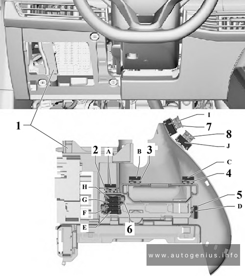
Individual fuses
Left-hand drive models, from July 2020
Fuse Box Location and Diagram
| № | Anps | Function / component |
|---|---|---|
| A | – | |
| B | – | |
| C | – | |
| D | – | |
| E | – | |
| F | – | |
| G | – | |
| H | – | |
| I | 15 A | Driver seat adjustment control unit Driver seat backrest fan Driver seat cushion fan |
| J | 15 A | Front passenger seat backrest fan Front passenger seat cushion fan |
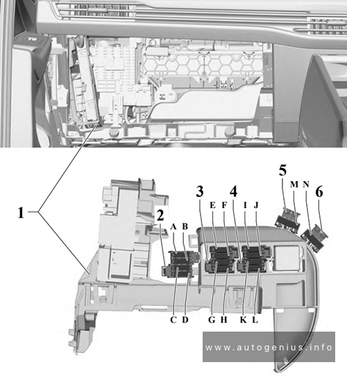
Left-hand drive models, from February 2021
Fuse Box Location and Diagram
| № | Amps | Function / component |
|---|---|---|
| A | 15 A | Driver seat adjustment control unit |
| B | – | – |
| C | – | – |
| D | 15 A | Driver seat backrest fan Driver seat cushion fan Operating unit for front left seat adjustment |
| E | 15 A | Front passenger seat backrest fan Front passenger seat cushion fan Operating unit for front right seat adjustment |
| F | – | – |
| H | – | – |
| G | 10 A | Special vehicle control unit Diagnostic connection 2 Coupling point for wheelchair lift Coupling point for two-way radio in special vehicle Coupling point for front right door Coupling point for front left door Coupling point for accident data recorder Coupling point for operating unit for special signals |
| I | – | – |
| J | – | – |
| K | 40 A | Coupling point for wheelchair lift Special vehicle control unit |
| L | 40 A | Special vehicle control unit Fuse 16 on relay and fuse carrier SRSH |
| M | – | – |
| N | – | – |
| O | – | – |
| P | – | – |
Right-hand drive models, from July 2020
Fuse Box Location and Diagram
| № | Amps | Function / component |
|---|---|---|
| A | – | – |
| B | – | – |
| C | – | – |
| D | – | – |
| E | – | – |
| F | – | – |
| G | – | – |
| H | – | – |
| I | – | – |
| J | – | – |
| K | – | – |
| L | – | – |
| M | 15 A | Front passenger seat backrest fan Front passenger seat cushion fan |
| N | 15 A | Driver seat adjustment control unit Driver seat backrest fan Driver seat cushion fan |
Fitting location of fuse for voltage converter
Fuse Box Location and Diagram

| № | Amps | Function / component |
|---|---|---|
| A | 125 A | Battery, 48 V Voltage converter (48 V/12V) |
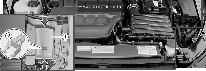
Engine Compartment Fuse Box
Fuse Box Location
Fuse Box Diagram (Fuse holder B -SB-)
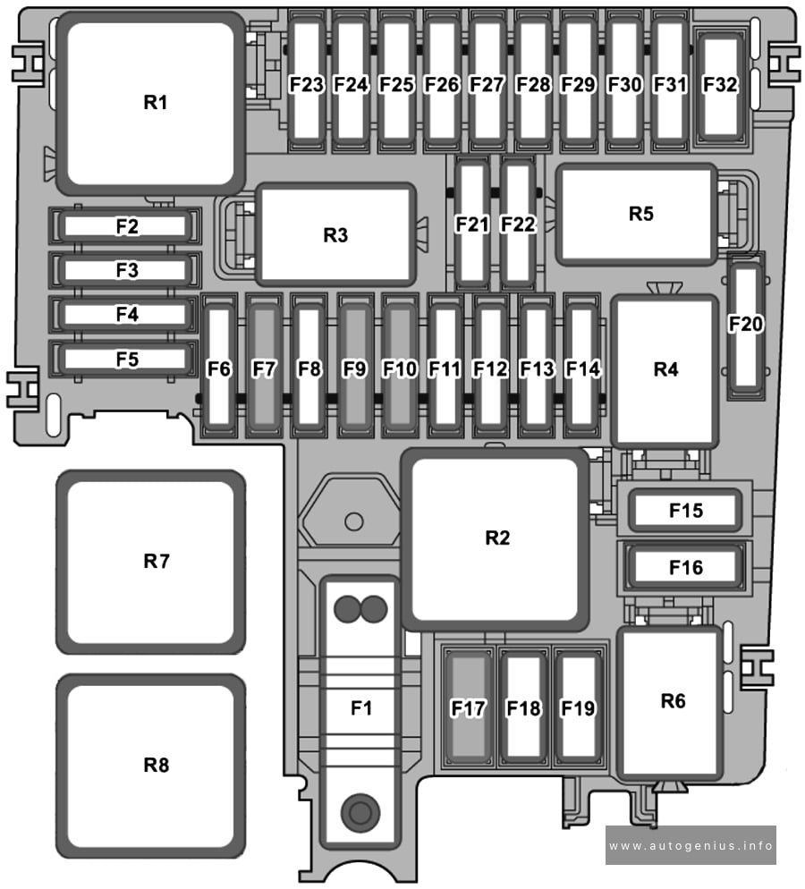
Assignment of the fuses in the engine compartment fuse box
| № | Amps | Function / component |
|---|---|---|
| SB1 | 400 A | Power steering control unit |
| SB2 | 7.5 A | Main relay (petrol) Terminal 30 voltage supply relay (diesel) Engine/motor control unit ABS control unit |
| SB3 | 20 A | Engine component current supply relay (2.0l petrol) |
| SB3 | 7.5 A | Relay for gas shut-off valves (natural gas engine) |
| SB4 | 15 A | Front left headlight |
| SB5 | 15 A | Front right headlight |
| SB6 | – | – |
| SB7 | 30 A | Auxiliary hydraulic pump 1 for gearbox oil |
| SB8 | 40 A | Brake servo |
| SB9 | 15 A | Horn relay |
| SB10 | 30 A | Wiper motor control unit |
| SB11 | – | – |
| SB12 | 15 A / 30 A | Mechatronic unit for dual clutch gearbox Automatic gearbox control unit |
| SB13 | 25 A | ABS control unit |
| SB14 | 20 A | Auxiliary heater control unit |
| SB15 | 40 A | ABS control unit |
| SB16 | – | – |
| SB17 | 40 A | Auxiliary air heater element (diesel) |
| SB18 | 40 A | Auxiliary air heater element (diesel) |
| SB19 | – | – |
| SB20 | 15 A | Axle differential lock control unit |
| SB21 | 7.5 A | Engine/motor control unit |
| SB22 | 30 A | Starter |
| SB23 | 15 A | Engine/motor control unit |
| SB24 | 7.5 A / 10 A | Radiator fan Oil level and oil temperature sender Activated charcoal filter solenoid valve 1 (petrol, natural gas engine) Exhaust camshaft control valve 1 (petrol, natural gas engine) Inlet camshaft control valve 1 (petrol, natural gas engine) Valve for oil pressure control (petrol, natural gas engine) Piston cooling jet control valve (petrol, natural gas engine) Fuel pressure regulating valve (diesel) Relay for reducing agent metering system (diesel) Automatic glow period control unit (diesel) Starter-alternator (models with 48 V system) Inlet cam actuator for cylinder 2 (1.5l petrol) Exhaust cam actuator for cylinder 2 (1.5l petrol) Inlet cam actuator for cylinder 3 (1.5l petrol) Exhaust cam actuator for cylinder 3 (1.5l petrol) Gas tank pressure sensor (natural gas engine) Relay for gas shut-off valves (natural gas engine) |
| SB25 | 10 A | Gas injection valve 1 (natural gas engine) Gas injection valve 2 (natural gas engine) Gas injection valve 3 (natural gas engine) Gas injection valve 4 (natural gas engine) |
| SB26 | 10 A | Heater element for crankcase breather (diesel) Valve for oil pressure control (diesel) Actuator for engine temperature regulation (diesel) Coolant regulating valve (diesel) Piston cooling jet control valve (diesel) Coolant circulation pump (2.0l petrol) Charge air cooling pump (petrol, natural gas engine) Auxiliary pump for heating (diesel) |
| SB27 | 10 A / 15 A | Particulate sensor (diesel) Lambda probe 1 after catalytic converter (petrol) Lambda probe 1 before catalytic converter (petrol) Control unit for NOx sender (diesel) Control unit 2 for NOx sender (diesel) Control unit 3 for NOx sender (diesel) Control unit 1 for particulate sensor (diesel) |
| SB28 | 20 A | Ignition coil 1 with output stage (1.5l petrol, 1.4l petrol) Ignition coil 2 with output stage (1.5l petrol, 1.4l petrol) Ignition coil 3 with output stage (1.5l petrol, 1.4l petrol) Ignition coil 4 with output stage (1.5l petrol, 1.4l petrol) Activated charcoal filter solenoid valve 1 (1.4l petrol) Inlet camshaft control valve 1 (1.4l petrol) Exhaust camshaft control valve 1 (1.4l petrol) Valve for oil pressure control (1.4l petrol) |
| SB29 | 15 A / 20 A | Fuel pump control unit |
| SB30 | – | – |
| SB31 | – | – |
| SB32 | – | – |
| R1 | Main relay | |
| R2 | High heat output relay (diesel) | |
| R3 | Horn relay | |
| R4 | Starter relay 1 | |
| R5 | Starter relay 2 | |
| R6 | Relay for gas shut-off valves (natural gas drive) Engine component current supply relay (2.0l petrol engine) |
|
| R7 | Automatic glow period control unit | |
| R8 | Low heat output relay |
High Power Fuses (Fuse holder A -SA-)
Fuse Box Location and Diagram
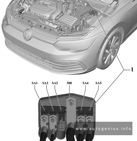
| № | Amps | Function / component |
|---|---|---|
| SA1 | 150 A | Fuse holder B |
| SA2 | 50 A | Radiator fan |
| SA3 | – | – |
| 508 | Battery | |
| SA4 | 125 A | Fuse holder C |
| SA5 | 125 A | Fuse holder C |
WARNING: Terminal and harness assignments for individual connectors will vary depending on vehicle equipment level, model, and market.