Opel Astra H – (2004 – 2009) – fuse and relay box diagram

Opel Astra H – (2004 – 2009) – fuse and relay box diagram

Year of production: 2004, 2005, 2006, 2007, 2008, 2009


The Opel Astra H, the third generation of the Opel Astra compact-class passenger car, was produced from 2004 to 2009 with both gasoline and diesel engine options. Also marketed as the Vauxhall Astra H, this model underwent a facelift during its production period. In this article, you will find information on the locations of the control units, detailed descriptions of the Astra H fuse boxes and relays, their diagrams.  Additionally, we will identify the fuse responsible for the cigarette lighter.


Engine compartment fuse box

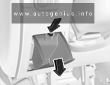
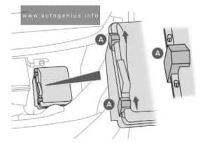
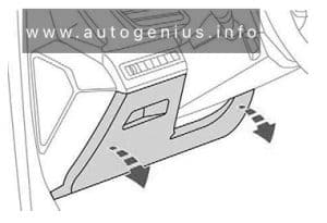
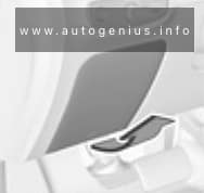
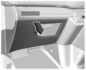
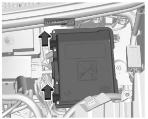
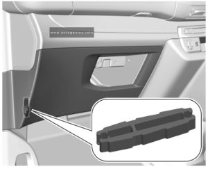
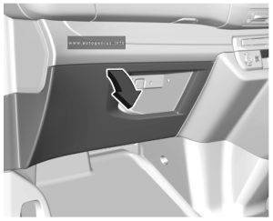
Insert a screwdriver into the opening as far as it will go and tilt it sideways. Open the cover upwards and remove. The fuse box has two different fuse assignments depending on the load compartment fuse box variant,

Fuse Box Diagram

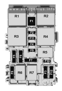
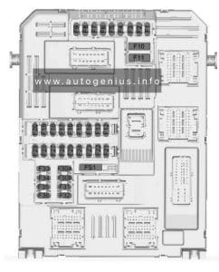
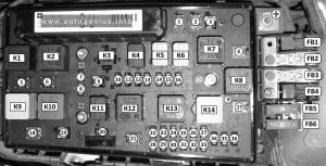
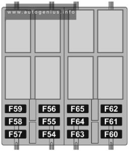
Opel Astra H (2004 - 2009) - fuse and relay diagram - engine compartment
Opel Astra H (2004 – 2009) – fuse and relay diagram – engine compartment


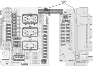
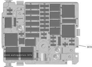
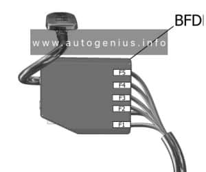
Assignment of the fuses in the engine compartment.

Amp Description
FB1 50A Electro Hydraulic Hard Top HT
FB2 80A Diesel (Glow time controller)
FB3 80A EGUR
FB4 30A Independent heater IH 100А Additional heater – electric, passenger compartment EH
FB5 80A REC / Rear Fuse Box
FB6 80A REC / Rear Fuse Box
F1 20A Anti-lock braking system (ABS)
F2 30A Anti-lock braking system (ABS)
F3 30A Heating system, interior ventilation, climate control (HVAC)
F4 30A Heating, ventilation and air conditioning (HVAC)
F5 30A or 40A Radiator fan
F6 20A or 30A or 40A Radiator fan
F7 10A Windscreen washers (front and rear)
20A (without REC) Central locking ZV
F8 15A Horn
10 (without REC) Central locking ZV, Front windscreen washer, rear WA
F9 25A Windscreen washers (front and rear)
25A (without REC) Heated rear window HFH (K17_X125)
F10 7,5A To the diagnostic connector DIAG
F11 7,5A Instruments
F12 5A Circulation pump
7,5A (without REC) Inf. ID Display, Twin Audio TWA Audio System, DAB Digital Broadcasting, TCV Voice Control Phone
F13 15A Fog lamp
5A Interior lamp IRL (K18_X125)
F14 30A Windscreen wiper (front)
F15 30A Windscreen wiper (rear)
F16 5A Engine control module / Open-Start / Stop system (without REC) ABS-ESP, Sound signal (K4_X125), Air conditioning, semi-automatic air conditioning, electronic climate control, Brake light switch, el. hydraulic rigid top
F17 25A Fuel filter heating (diesel models)
F18 25A Starter
F19 30A Electronic gearbox equipment
F20 10A Air conditioner compressor, Horn (K4_X125)
F21 20A Engine control module (ECM)
F22 7.5A Engine control module (ECM)
F23 10A Adaptive headlight system (AFL), headlamp leveling
F24 15A Fuel pump
F25 15A Electronic gearbox equipment
F26 10A Engine control module (ECM)
F27 5A Power steering
F28 5A Electronic equipment of a transmission
F29 7.5A Electronic equipment of gearbox
7.5A (with REC) Control unit gearbox Automatic / Easytronic
F30 10A Engine control module (ECM)
F31 10A Adaptive headlight system (AFL). Headlamp leveling
15A (without REC) Rear window wiper (K56)
F32 5A Brake system fault indicator lamp, air conditioning, clutch pedal switch
F33 5A Headlight leveling, Adaptive Forward Lighting (AFL), Outdoor light control unit
F34 7.5A Steering column module control unit
F35 20A Infotainment system
F36 7.5A Mobile phone, digital radio receiver, Twin Audio system, multifunction display
15A (without REC) Cigarette lighter
К1 (K11_X125) Radiator fan (FE5, FE6)
К2 (K12_X125) Radiator fan (FE5, FE6)
КЗ (K7_X125) (with REC) Headlight washer pump (FE9)
K4 (K16_X125) (with REC) Fog lights, front (FE13)
K4 (K18_X125) (K18_X125) (without REC) Disable download (interior lighting, etc.) (FE13)
К5 K5 (K5_X125) Wiper, windshield, low / high (FE14, FE15)
К6 (K6_X125) Wiper, windshield, ON / OFF (FE14, FE15)
К7 (K15_X125) Fan, passenger compartment – Air Conditioning / Heating (FE4)
К8 (K14_X125) (with REC) Filter heating (Diesel) (FE17)
(K8_X125) (without REC) Compressor, air conditioning (FE17)
K9 (K1_X125) Starter (FE18, K3_X125)
К10 (K13_X125) Radiator fan (FE5, FE6)
К11 (K8_X125) (with REC) Compressor, air conditioning (FE20, FE32)
(K4_X125) (without REC) Horn sound signal (FE20, FE16)
К12 (K2_X125) Engine management controller (on FE21, FE26, FE32)
К13 (K10_X125) Fuel pump (FE24)
К14 (K3_X125) Pin 15 (on K1_X125, FE23, FE24, FE25, FE27, FE29, FE30, FE31, FE33)
К15 Heater fan relay
К16 Fog light relay

Individual relay elements can be located outside the main unit

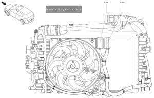
Opel Astra H (2004 - 2009) - fuse and relay diagram - engine compartment (relays)
Opel Astra H (2004 – 2009) – fuse and relay diagram – engine compartment (relays)


Assignment of the relays in the engine compartment

Number Description
K30A Relay Radiator fan (FE5, FE6)
K30B Relay K30B Relay – radiator fan (FE5, FE6)
K84LD / RD Relay Hydraulic Unit (Convertible Top) (FB1)
K93 Relay Unlocking the gear lever (Automatic transmission AF17 / 4, AF22 / 4)


Luggage compartment fuse box

Fuse Box Location

Located behind the left-hand side trim.


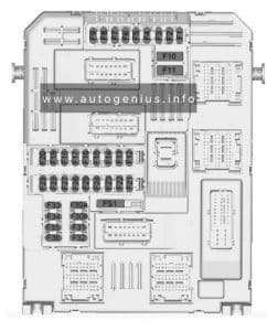
Type 1

Fuse Box Diagram

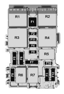
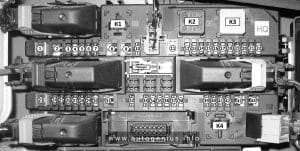
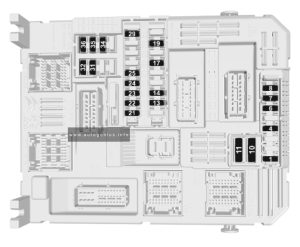
Opel Astra H (2004 - 2009) - fuse and relay diagram - luggage compartment (type 1)
Opel Astra H (2004 – 2009) – fuse and relay diagram – luggage compartment (type 1)

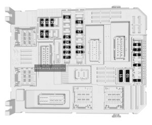
Assignment of the fuses in the luggage compartment (type 1)

Amp Description
1 25A/30A Front power windows
2 Not Used
3 7.5A Instrument panel
4 5A Heating / Air Conditioning / Climate Control (HVAC)
5 7.5A Airbag
6 Not Used
7 Not Used
8 Not Used
9 Not Used
10 Not Used
11 25A Rear window heating (rear window glass)
12 15A Windshield wiper of a window of a door of a back
13 5A Parking aid
14 7.5A Air Conditioning System
15 Not Used
16 5A Right front seat occupancy sensor, Open&Start system
17 5A Rain Sensor / Air Quality Sensor / Tire Pressure Monitoring System / Interior Rearview Mirror
18 5A Instruments / switches
19 Not Used
20 10A Damping Dynamic Control System (CDC)
21 7.5A External rear-view mirrors heater
22 20A/25A Sliding roof
23 25A/30A Rear power windows
24 7.5A Diagnostic Connector
25 Not Used
26 7.5A Folding exterior mirrors
27 5A Ultrasonic sensor, anti-theft alarm system
28 Not Used
29 15A Cigar lighter / Front power outlet
30 10A/15A Rear socket for connecting additional electrical appliances
31 Not Used
32 Open & Start system
33 15A Open&Start system
34 25A Sliding roof
35 10A/15A Rear socket for connecting additional electrical appliances
36 20A Towbar socket
37 5A Interior lighting
38 25A/30A Central lock, Output “30”
39 15A Front left seat heater
40 15A Front right seat heater
41 Not Used
42 Not Used
43 Not Used
44 Not Used
RELAYS
К2 (K3_X131) Relay Heated rear window, mirrors (on FR11, FR21), (from FB5, FB6)
К3 (K1_X131) Relay Pin 15 (on FR12, FR13, FR14, FR16, FR17, FR18, FR20)
К4 (K2_X131) Relay Terminal 15a (on FR39, FR40)

Type 1

Fuse Box Diagram

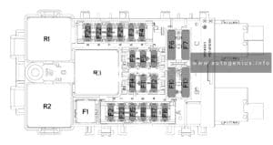
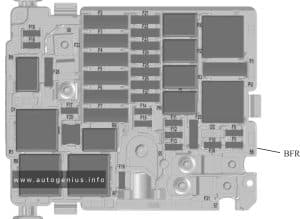
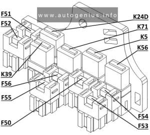
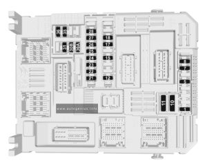
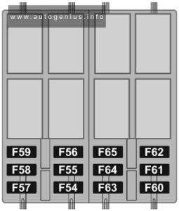
Opel Astra H (2004 - 2009) - fuse and relay diagram - luggage compartment (type 2)
Opel Astra H (2004 – 2009) – fuse and relay diagram – luggage compartment (type 2)


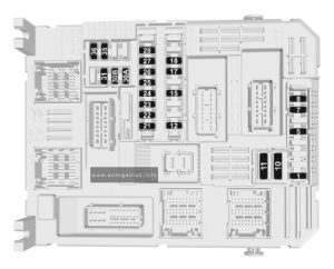
Assignment of the relays in the engine compartment (type 2)

Amp Description
F50 10A AC air conditioner (on relay K5)
F51 15 Fog lights (front) (on relay K39)
F52 15 Auxiliary socket (rear cigarette lighter) ACS
F53 7.5A Heated mirrors
F54 30A Front windows FHF
F55 30A Rear windows FHR
F56 7,5A Taillights (on K71), Lock without handle (on K24D)
K5 RELAY Relay – compressor, air conditioning (FE33, F50)
K24D RELAY Dead block relay (F56)
K39 RELAY Relay – fog lamp, front (F51)
K56 RELAY Relay – wiper, rear window (FE31, FE33)
K71 RELAY Relay – reversing light (F56, FE33)

WARNING: Terminal and harness assignments for individual connectors will vary depending on vehicle equipment level, model, and market.

Opel Ampera-e (2017 – 2020) – fuse and relay box diagram

Opel Ampera-e (2017 – 2019) – fuse and relay box diagram

Year of production: 2017, 2018, 2019, 2020


The Opel Ampera-e, a battery-electric subcompact hatchback, was manufactured between 2017 and 2019. This article provides fuse box diagrams for the 2017, 2018, and 2019 models, along with details on the fuse panel locations within the vehicle and the specific functions of each fuse (fuse layout).


Passenger Compartment Fuse Box

Fuse Box Location

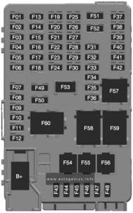
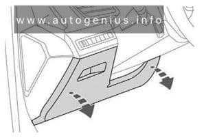
The fuse box is located on the driver’s side behind a cover in the instrument panel.

Opel Ampera-e (2017 - 2019) - fuse and relay location - passenger compartment
Opel Ampera-e (2017 – 2019) – fuse and relay location – passenger compartment


Fuse Box Diagram

Opel Ampera-e (2017 - 2019) - fuse and relay diagram - passenger compartment
Opel Ampera-e (2017 – 2019) – fuse and relay diagram – passenger compartment


Assignment of the fuses in the passenger compartment

Usage
1 Video processing module
2 Indicator light solar sensor
3 Side blind zone alert
4 Passive entry, passive start
5 Central gateway module
6 Body control module 4
7 Body control module 3
8 Body control module 2
9 Body control module 1
10 Trailer interface module 1
11 Amplifier
12 Body control module 8
13 Data link connector 1
14 Automatic parking assist
15 2016-2017: Data link connector 2
16 Single power inverter module 1
17 Body control module 6
18 Body control module 5
19
20
21
22
23 USB
24 Wireless charging module
25 Reflected LED alert display
26 Heated steering wheel
27
28 Instrument cluster 2
29 Trailer interface module 2
30 Headlight levelling device
31 OnStar
32
33 Heating, ventilation, and air conditioning module
34
35 Instrument panel cluster 1
36 Regen on demand / Radio
37
38
39
40
41
42
43 Body control module 7
44 Sensing and diagnostic module
45 Front camera module
46 Vehicle integration control module
47 Single power inverter module 2
48 Electric steering column lock
49 Auxiliary jack
50 Steering wheel controls
51 Steering wheel controls backlighting
52 Smartphone remote function module
53 Auxiliary power outlet
54
55 Logistic
56
57
58 Logistics relay
59
60 Accessory/Retained accessory power relay

Engine compartment fuse box

Fuse Box Location

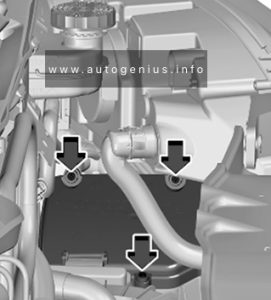
The fuse box is located at the left front side of the engine compartment.

Opel Ampera-e (2017 - 2019) - fuse and relay location - engine compartment
Opel Ampera-e (2017 – 2019) – fuse and relay location – engine compartment


Fuse Box Diagram

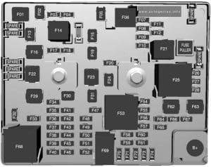
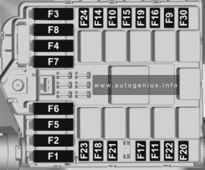
Opel Ampera-e (2017 - 2019) - fuse and relay diagram - engine compartment
Opel Ampera-e (2017 – 2019) – fuse and relay diagram – engine compartment


Assignment of the fuses in the engine compartment

Usage
1
2 Power window rear
3
4 Rechargeable energy storage system 1
5
6
7 Left high-beam headlight
8 Right high-beam headlight
9 Left low-beam headlight
10 Right low-beam headlight
11 Horn
12
13 Front wiper motor driver
14 Tailgate
15 Front wiper motor co-driver
16 Electronic brake control module supply electronics
17 Rear wiper
18 Tailgate
19 Seat module front
20 Washer
21 2016-2017: HID light
22 Linear power module
23 Electronic brake control module supply motor
24 Seat module rear
25 Powertrain
26 Transmission range control module
27 Aero shutter
28 Auxiliary oil pump
29 E-booster motor source
30 Front power windows
31 In-panel bussed electrical centre
32 Rear window defogger
33 Heated exterior rear view mirror
34 Pedestrian friendly alert function
35
36
37 Current sensor
38 Rain sensor
39
40 E-booster (ECU)
41 Power line communication module
42 Automatic occupant sensing
43 Window switch
44 Rechargeable energy storage system
45 Vehicle integration control module
46 Integrated chassis control module
47 Headlight levelling device
48 Integrated chassis control module
49 Interior rear view mirror
50
51 E-booster
52 Rear camera
53 Run/Crank
54 A/C control module
55 Rechargeable energy storage system pump
56
57 Power electronics coolant pump
58 Engine control module
59 Electric steering column lock
60 HVAC electric heater
61 On-board charging module
62 Transmission range control module 1
63 Electric cooling fan
64 Engine control module
65 Auxiliary heater pump
66 Powertrain relay
67 Drive unit controller
68 Rear window defogger
69 Second run/Crank relay
70 A/C control module
71
72 Transmission range control module
73 Single power inverter module
74

WARNING: Terminal and harness assignments for individual connectors will vary depending on vehicle equipment level, model, and market.
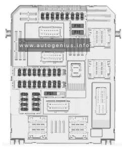
Opel Vivaro C (2020 – 2023) – fuse and relay box diagram

Opel  Vivaro C (2020 – 2023) – fuse and relay box diagram

Year of production: 2020, 2021, 2022, 2023


This article covers the third-generation Opel Vivaro C (Vauxhall Vivaro C), available from 2020 to the present. It includes fuse box diagrams for the 2020, 2021, 2022, and 2023 Opel Vivaro C models, provides information on the locations of the fuse panels within the vehicle, and details the assignment and layout of each fuse (fuse layout).


Fuse extractor

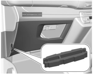
A fuse extractor may be located behind the passenger compartment fuse box cover. Unclip the cover by pulling at the top left, then right. Disengage the cover completely and turn it over.

Opel Vivaro C - fuse and relay box location - passenger compartment (fuse extractor)
Opel Vivaro C – fuse and relay box location – passenger compartment (fuse extractor)


The extractor has two sides, each side is designed for a different type of fuses.


Passenger Compartment Fuse Panel

Fuse Box Location

The fuse box is located behind a cover in the instrument panel at the left side. Unclip the cover by pulling at the top left, then right. Disengage the cover completely and turn it over.

Opel Vivaro C - fuse and relay box location - passenger compartment
Opel Vivaro C – fuse and relay box location – passenger compartment


Fuse Box Diagram

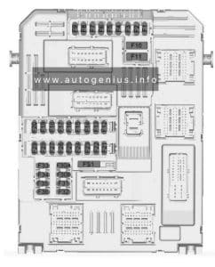
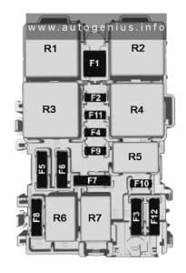
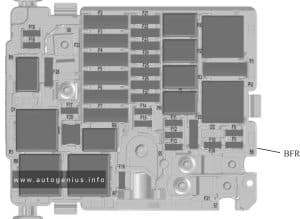
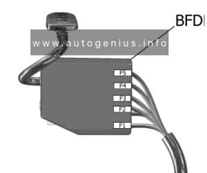
Version 1 (Eco)
Opel Vivaro C - fuse and relay box location - passenger compartment (version 1 (eco))
Opel Vivaro C – fuse and relay box location – passenger compartment (version 1 (eco))


Assignment of the fuses in the instrument panel (Version 1 (Eco))

Circuit
1 Clutch switch, power steering
4 Horn
5 Front and rear screenwash pump
6 Front and rear screenwash pump
7 Rear power outlet
8 Rear window wipers
10/11 Central locking system
13 Head-up display, climate controls, Infotainment system controls, gear selector
14 Anti-theft alarm system, telematic unit
17 Instrument cluster
19 Steering wheel controls
21 Anti-theft system or electronic key system
22 Front camera, rain and light sensor
23 Seat belt reminder
24 Parking assist, Infotainment system, rear view camera
25 Airbags
29 Infotainment system
31 Infotainment system (+ battery)
32 Front power outlet
34 Interior mirror, blind spot monitoring system, door mirror controls
35 Heated washer jets, headlight range adjustment
36 Interior lights, torch charger

Version 2 (Full)
Opel Vivaro C - fuse and relay box location - passenger compartment (version 2 (full))
Opel Vivaro C – fuse and relay box location – passenger compartment (version 2 (full))


Assignment of the fuses in the instrument panel (Version 2 (Full))

Circuit
1 Anti-theft system or electronic key system
5 Parking assist, Infotainment system, rear view camera
7 Rear climate controls, audio system amplifier
8 Rear window wipers
10/11 Central locking system
12 Anti-theft alarm system
17 Rear power outlet
18 Telematic unit
21 Interior lights, torch charger
22 Interior lights, glovebox light
23 Blind spot monitoring system, door mirror controls
24 Steering wheel controls
25 Headlight range adjustment
26 Seat belt reminder
27 Front camera, rain and light sensor
28 Head-up display, front climate controls, Infotainment system controls, gear selector
30A or 30B Audio system (+ battery)
31 Airbag
33 Front power outlet
35 Instrument cluster
36 Infotainment system

Engine Compartment Fuse Box

Fuse Box Location

The fuse box is in the front left of the engine compartment. Disengage the cover and remove it.

Opel Vivaro C - fuse and relay box location - engine compartment
Opel Vivaro C – fuse and relay box location – engine compartment


Assignment of the fuses in the engine compartment

Circuit
12 Heated washer jets
14 Front and rear screenwash pump
15 Front radar system, electric power steering
17 Built-in systems interface
19 Front wiper motor
20 Front and rear screenwash pump
21 Headlight wash pump
22 Horn
23 Right high beam
24 Left high beam

WARNING: Terminal and harness assignments for individual connectors will vary depending on vehicle equipment level, model, and market.
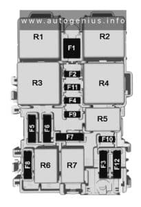
Vauxhall Vivaro C (2020 – 2023) – fuse and relay box diagram

Vauxhall Vivaro C (2020 – 2023) – fuse and relay box diagram

Year of production: 2020, 2021, 2022, 2023


This article covers the third-generation Opel Vivaro C (Vauxhall Vivaro C), available from 2020 to the present. It includes fuse box diagrams for the 2020, 2021, 2022, and 2023 Opel Vivaro C models, provides information on the locations of the fuse panels within the vehicle, and details the assignment and layout of each fuse (fuse layout).


Fuse extractor

A fuse extractor may be located behind the passenger compartment fuse box cover. Unclip the cover by pulling at the top left, then right. Disengage the cover completely and turn it over.

Vauxhall Vivaro C - fuse and relay box location - passenger compartment (fuse extractor)
Vauxhall Vivaro C – fuse and relay box location – passenger compartment (fuse extractor)


The extractor has two sides, each side is designed for a different type of fuses.


Passenger Compartment Fuse Panel

Fuse Box Location

The fuse box is located behind a cover in the instrument panel at the left side. Unclip the cover by pulling at the top left, then right. Disengage the cover completely and turn it over.

Vauxhall Vivaro C - fuse and relay box location - passenger compartment
Vauxhall Vivaro C – fuse and relay box location – passenger compartment


Fuse Box Diagram

Version 1 (Eco)
Vauxhall Vivaro C - fuse and relay box location - passenger compartment (version 1 (eco))
Vauxhall Vivaro C – fuse and relay box location – passenger compartment (version 1 (eco))


Assignment of the fuses in the instrument panel (Version 1 (Eco))

Circuit
1 Clutch switch, power steering
4 Horn
5 Front and rear screenwash pump
6 Front and rear screenwash pump
7 Rear power outlet
8 Rear window wipers
10/11 Central locking system
13 Head-up display, climate controls, Infotainment system controls, gear selector
14 Anti-theft alarm system, telematic unit
17 Instrument cluster
19 Steering wheel controls
21 Anti-theft system or electronic key system
22 Front camera, rain and light sensor
23 Seat belt reminder
24 Parking assist, Infotainment system, rear view camera
25 Airbags
29 Infotainment system
31 Infotainment system (+ battery)
32 Front power outlet
34 Interior mirror, blind spot monitoring system, door mirror controls
35 Heated washer jets, headlight range adjustment
36 Interior lights, torch charger

Version 2 (Full)
Vauxhall Vivaro C - fuse and relay box location - passenger compartment (version 2 (full))
Vauxhall Vivaro C – fuse and relay box location – passenger compartment (version 2 (full))


Assignment of the fuses in the instrument panel (Version 2 (Full))

Circuit
1 Anti-theft system or electronic key system
5 Parking assist, Infotainment system, rear view camera
7 Rear climate controls, audio system amplifier
8 Rear window wipers
10/11 Central locking system
12 Anti-theft alarm system
17 Rear power outlet
18 Telematic unit
21 Interior lights, torch charger
22 Interior lights, glovebox light
23 Blind spot monitoring system, door mirror controls
24 Steering wheel controls
25 Headlight range adjustment
26 Seat belt reminder
27 Front camera, rain and light sensor
28 Head-up display, front climate controls, Infotainment system controls, gear selector
30A or 30B Audio system (+ battery)
31 Airbag
33 Front power outlet
35 Instrument cluster
36 Infotainment system

Engine Compartment Fuse Box

Fuse Box Location

The fuse box is in the front left of the engine compartment. Disengage the cover and remove it.

Vauxhall Vivaro C - fuse and relay box location - engine compartment
Vauxhall Vivaro C – fuse and relay box location – engine compartment


Assignment of the fuses in the engine compartment

Circuit
12 Heated washer jets
14 Front and rear screenwash pump
15 Front radar system, electric power steering
17 Built-in systems interface
19 Front wiper motor
20 Front and rear screenwash pump
21 Headlight wash pump
22 Horn
23 Right high beam
24 Left high beam

WARNING: Terminal and harness assignments for individual connectors will vary depending on vehicle equipment level, model, and market.
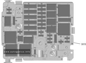
Vauxhall Movano C (2021 – 2023) – fuse and relay box diagram

Vauxhall Movano C (2021 – 2023) – fuse and relay box diagram

Year of production: 2021, 2022, 2023


This article focuses on the third-generation Opel Movano (Vauxhall Movano), available from 2021 to the present. It includes fuse box diagrams for the 2021, 2022, and 2023 Opel Movano C models, provides details on the locations of the fuse panels within the vehicle, and explains the function and layout of each fuse (fuse layout).


Passenger Compartment Fuse Panel

Fuse Box Location

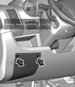
The fuse box is located behind a cover in the instrument panel at the left side. Remove the screws with the screwdriver and remove the cover to access the fuses.

Vauxhall Movano C - fuse and relay box location - passenger compartment
Vauxhall Movano C – fuse and relay box location – passenger compartment


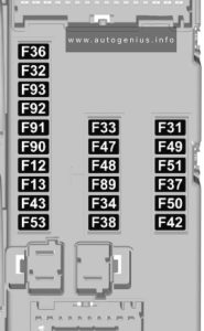
Fuse Box Diagram

Vauxhall Movano C - fuse and relay box diagram - passenger compartment
Vauxhall Movano C – fuse and relay box diagram – passenger compartment


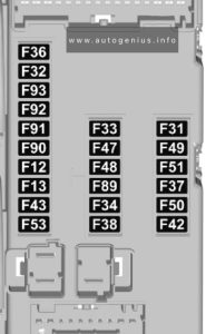
Assignment of the fuses in the instrument panel 

Circuit
12 Right low beam
13 Left low beam
31 Instrument panel control unit
32 Interior lights
33 Stop-start system
34 Interior lights
Minibus – Hazard warning flashers
36 Infotainment system / Climate control / Alarm / Tachograph / Battery disconnecting control unit / Additional heater / Tyre pressure monitoring / Stop-start system
37 Brake system / Instrument panel
38 Central locking system
42 Electronic stability control system / Traction control system / ABS / Brake lights
43 Windscreen washer
47 Electric windows
48 Electric windows
49 Parking assist / Infotainment system / Steering wheels controls / Central and side control panels / Auxiliary control panel / Battery disconnecting control unit / Trailer hitch / Rain sensor / Stop-start system
50 Airbag system / Pretensioners
51 Tachograph / Power steering / Climate control system / Reversing lights / Navigation system / Lane departure warning / Rear view camera / Headlights
53 Insrument panel
89
90 Left high beam
91 Right high beam
92 Left front fog light
93 Right front fog light

Additional Fuse Box

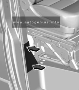
Fuse Box Location

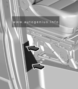
There is a fuse box located in the right B-pillar.

Vauxhall Movano C- fuse and relay box location - passenger compartment (additional box)
Vauxhall Movano C- fuse and relay box location – passenger compartment (additional box)


Fuse Box Diagram

Vauxhall Movano C- fuse and relay box diagram - passenger compartment (additional box)
Vauxhall Movano C- fuse and relay box diagram – passenger compartment (additional box)


Assignment of the fuses in the additional fuse box

Circuit
54 Climate control system
55 Seat heating
56 Power outlet rear passenger
57 Additional heater
58 Heated rear window
59 Heated rear window
60
61
62
63 Additional heater
64
65 Additional heater

Engine Compartment Fuse Box

Fuse Box Location

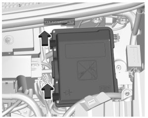
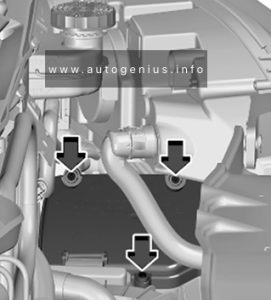
The fuse box is in the front left of the engine compartment. Remove the screws and tilt the casing to access the fuses.

Vauxhall Movano C- fuse and relay box location - engine compartment
Vauxhall Movano C- fuse and relay box location – engine compartment


Fuse Box Diagram

Vauxhall Movano C- fuse and relay box diagram - engine compartment
Vauxhall Movano C- fuse and relay box diagram – engine compartment


Assignment of the fuses in the engine compartment

Circuit
1 ABS
2 Fuel system
3 Ignition switch
4 Fuel system
5 Climate control system
6 Climate control system
7 Climate control system
8 Climate control system
9 Power outlet rear
10 Horn
14 Power outlet front
15 Cigarette lighter
19 Climate control system
20 Windscreen washer
21 Fuel system
23 ABS
24 Auxiliary control panel / Electric mirrors
30 Climate control system

WARNING: Terminal and harness assignments for individual connectors will vary depending on vehicle equipment level, model, and market.

Opel Movano C (2021 – 2023) – fuse and relay box diagram

Opel Movano C (2021 – 2023) – fuse and relay box diagram

Year of production: 2021, 2022, 2023


This article focuses on the third-generation Opel Movano (Vauxhall Movano), available from 2021 to the present. It includes fuse box diagrams for the 2021, 2022, and 2023 Opel Movano C models, provides details on the locations of the fuse panels within the vehicle, and explains the function and layout of each fuse (fuse layout).
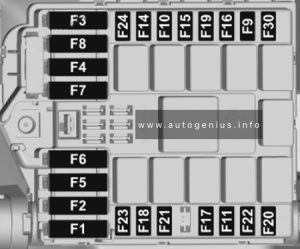
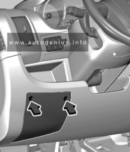
 

Passenger Compartment Fuse Panel

Fuse Box Location

The fuse box is located behind a cover in the instrument panel at the left side. Remove the screws with the screwdriver and remove the cover to access the fuses.

Opel Movano C- fuse and relay box location - passenger compartment
Opel Movano C – fuse and relay box location – passenger compartment


Fuse Box Diagram

Opel Movano C - fuse and relay box diagram - passenger compartment
Opel Movano C – fuse and relay box diagram – passenger compartment


Assignment of the fuses in the instrument panel 

Circuit
12 Right low beam
13 Left low beam
31 Instrument panel control unit
32 Interior lights
33 Stop-start system
34 Interior lights
Minibus – Hazard warning flashers
36 Infotainment system / Climate control / Alarm / Tachograph / Battery disconnecting control unit / Additional heater / Tyre pressure monitoring / Stop-start system
37 Brake system / Instrument panel
38 Central locking system
42 Electronic stability control system / Traction control system / ABS / Brake lights
43 Windscreen washer
47 Electric windows
48 Electric windows
49 Parking assist / Infotainment system / Steering wheels controls / Central and side control panels / Auxiliary control panel / Battery disconnecting control unit / Trailer hitch / Rain sensor / Stop-start system
50 Airbag system / Pretensioners
51 Tachograph / Power steering / Climate control system / Reversing lights / Navigation system / Lane departure warning / Rear view camera / Headlights
53 Insrument panel
89
90 Left high beam
91 Right high beam
92 Left front fog light
93 Right front fog light

Additional Fuse Box

Fuse Box Location

There is a fuse box located in the right B-pillar.

Opel Movano C- fuse and relay box location - passenger compartment (additional box)
Opel Movano C- fuse and relay box location – passenger compartment (additional box)


Fuse Box Diagram

Opel Movano C- fuse and relay box diagram - passenger compartment (additional box)
Opel Movano C- fuse and relay box diagram – passenger compartment (additional box)


Assignment of the fuses in the additional fuse box

Circuit
54 Climate control system
55 Seat heating
56 Power outlet rear passenger
57 Additional heater
58 Heated rear window
59 Heated rear window
60
61
62
63 Additional heater
64
65 Additional heater

Engine Compartment Fuse Box

Fuse Box Location

The fuse box is in the front left of the engine compartment. Remove the screws and tilt the casing to access the fuses.

Opel Movano C- fuse and relay box location - engine compartment
Opel Movano C- fuse and relay box location – engine compartment


Fuse Box Diagram

Opel Movano C- fuse and relay box diagram - engine compartment
Opel Movano C- fuse and relay box diagram – engine compartment


Assignment of the fuses in the engine compartment

Circuit
1 ABS
2 Fuel system
3 Ignition switch
4 Fuel system
5 Climate control system
6 Climate control system
7 Climate control system
8 Climate control system
9 Power outlet rear
10 Horn
14 Power outlet front
15 Cigarette lighter
19 Climate control system
20 Windscreen washer
21 Fuel system
23 ABS
24 Auxiliary control panel / Electric mirrors
30 Climate control system

WARNING: Terminal and harness assignments for individual connectors will vary depending on vehicle equipment level, model, and market.