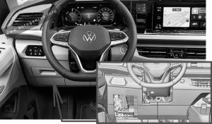
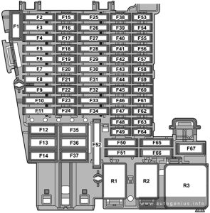
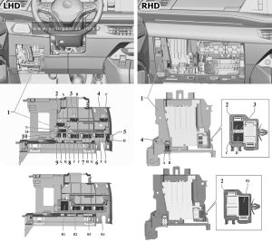
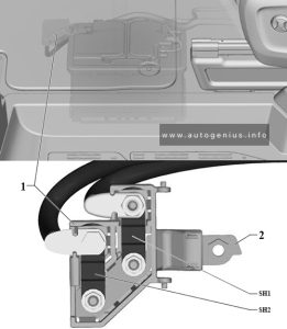
Alfa Romeo 155 (1992 – 1998) – fuse box diagram

Alfa Romeo 155 (1992 – 1998) – fuse box diagram

Year of production: 1992, 1993, 1994, 1995, 1996, 1997, 1998


Alfa Romeo 155 is a mid-size sedan produced in 1992, 1993, 1994, 1995, 1996, 1997 and 1998. In this article, we will show a designation of fuses and relays Alfa Romeo 155 with box diagrams and their locations. Note the cigarette lighter fuse.

Passenger Compartment Fuse Panel

Version 1

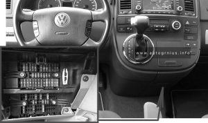
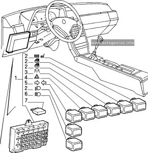
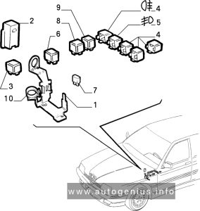
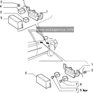
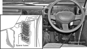
The fuse and relay box is located in the passenger compartment on the left.

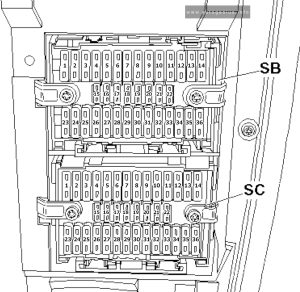
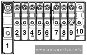
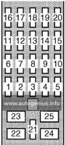
Alfa Romeo 155 (1992 - 1998) - fuse box diagram - passenger compartment (version 1)
Alfa Romeo 155 (1992 – 1998) – fuse box diagram – passenger compartment (version 1)
No. Circuit protected
Daytime running light relay I
Headlight washer relay (black)
Suspension relay (brown)
Tailgate/Trunk Compartment Release Relay (Red)
Daytime running light relay II
Coolant fan motor Relay (White)
Sunroof Motor Relay (White)
20 Washing/wiping the headlights
30 Suspension adjustment
30 Boot release
25 Electric windows
25 Electric windows
25 Electric windows
10 ABS

Version 2

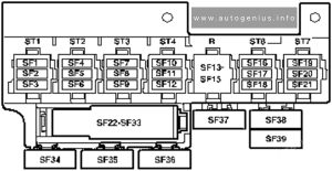
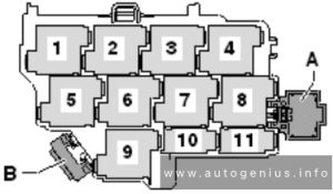
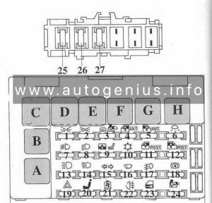
Alfa Romeo 155 (1992 - 1998) - fuse box diagram - passenger compartment (version 2)
Alfa Romeo 155 (1992 – 1998) – fuse box diagram – passenger compartment (version 2)
Fuse A Circuit protected
1 10 Hazard warning lights
2 20 Horns, Cigar lighters, Stoplights, Boot release, Radio
3 20 Windscreen wipers
4 20 Roof light timer
5 10 Control lighting, Rear left and front right sidelights, RH numberptale light
6 10 Control lighting, Rear right and front left sidelights, LH numberptale light
7 10 RH dipped beam headlight
8 10 LH dipped beam headlight
9 10 RH main beam headlight
10 10 LH main-beam headlight (+ warning lamp)
11 7,5 Rear foglamp (+ warning lamp)
12 30 Heated rear window (+ warning lamp), Door mirror defrosters
13 20 Heating/air conditioning fan, Seat warming, Rear and front power windows, Radio
14 20 Engine cooling fan (6V)
25 Electric fan for radiator cooling
15 10 Dashboard, Check Panel, Windscreen washers, Headlight washers, Reversing lights, Controlled damping suspension solenoid valves, Air conditioning compressor control, Engine electric fan control
16 7,5 Interior lights, Clock, Air conditioning control unit
17 7,5 Direction indicators, Door mirror adjustment, Controlled damping suspension
18 20 Door locks
19 20 Front foglamps (+ warning lamp)
Relay
N11 Door locking control unit
N13 Hazard warning lights and direction indicators intermittence
N14 Electronic windscreen wiper intermittence
I2 Heated rear window relay
I3 Horn relay
I17 Fog-light relay
I25 Rear fog light relay
I35 Key-operated supply relay
I49 Dipped beam headlight
I50 Main beam headlight
I64 Sidelights relay

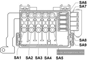
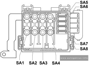
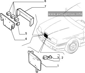
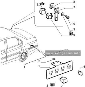
Auxiliary Fusebox

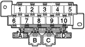
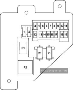
Alfa Romeo 155 (1992 - 1998) - fuse box diagram - auxiliary fuse box
Alfa Romeo 155 (1992 – 1998) – fuse box diagram – auxiliary fuse box
A Color Circuit protected
20 Black Headlight washer intermittence
25 Brown Passenger side power window
10 Red ABS
25 Blue Rear power windows
30 Green Electric seat adjustment
30 Red Boot release
20 Brown Controlled damping suspension
30 White Sunroof
Black Timer for headlight washer
Green Relay for radiator fan (only for TS model)

Engine compartment

There are usually two fuses and relay boxes. The first is located near the headlight and radiator cap under the protective casing.

Fuse box no. 1

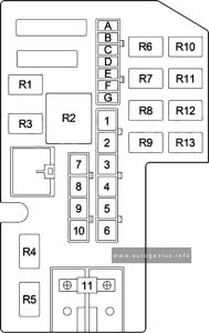
Alfa Romeo 155 (1992 - 1998) - fuse box diagram - engine compartment (fuse box no.1)
Alfa Romeo 155 (1992 – 1998) – fuse box diagram – engine compartment (fuse box no.1)
No. A Fuse component
F1 7,5 Fuel pump
F2 7,5 Lambda probe
F3 3 Engine control module
Relay
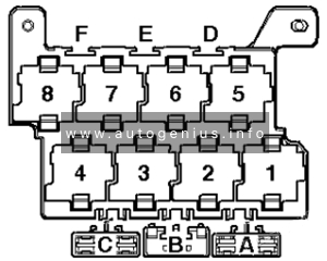
1 Engine Control Module 1 Relay
2 Timing relay
3 Fuel pump relay
4 Engine control module relay 2

Fuse box no. 2

The second one is near the ABS sensor above the brake cylinder.

Alfa Romeo 155 (1992 - 1998) - fuse box diagram - engine compartment (fuse box no.2)
Alfa Romeo 155 (1992 – 1998) – fuse box diagram – engine compartment (fuse box no.2)
No. A Fuse component
F1 30 A/C fan motor
F2 40 A/C cooling fan
F3 15 A/C compressor
Relay
1 A/C condenser fan motor relay
2 A/C condenser fan timer relay
3 A/C compressor clutch relay
4 Air conditioner relay


Fuse box no. 3

For V16 and 2.5 versions only, a third block has been added.

No. A Fuse component
F1 7,5 Lambda probe
F2 15 Motronic system
Relay
1 Engine Control Module I Relay
2 Fuel pump relay
3 Engine Control Module II Relay

1.8-2.0 TS Model

The following fuses are housed on a bracket located between the battery and the air-flow meter.

Alfa Romeo 155 (1992 - 1998) - fuse box diagram - engine compartment (1.8-2.0 TS Model)
Alfa Romeo 155 (1992 – 1998) – fuse box diagram – engine compartment (1.8-2.0 TS Model)
Number Circuit protected
1 Control unit power supply
2 Lambda probe (for vehicles equipped with catalytic converter)
3 Fuel pump
Relay
R1 Fuel pump relay
R2 Main relay
R3 Timing variator relay
R4 Relay for services

2.4 V6 model

The following fuses are located in a box located on the rear wall of the engine compartment next to the tank

Alfa Romeo 155 (1992 - 1998) - fuse box diagram - engine compartment (2.4 V6 model)
Alfa Romeo 155 (1992 – 1998) – fuse box diagram – engine compartment (2.4 V6 model)
Number Fuse component
1 Lambda probe (for vehicles equipped with catalytic converter)
2 Fuel pump
Relay
R1 Fuel pump relay
R2 Main relay
R3 Relay for services

Heating – ventilation system

The following fuses are housed in the rear left-hand part of the engine compartment next to the brake-clutch fluid reservoir.

Alfa Romeo 155 (1992 - 1998) - fuse box diagram - engine compartment (heating - ventilation system)
Alfa Romeo 155 (1992 – 1998) – fuse box diagram – engine compartment (heating – ventilation system)
No. A Fuse component
1 50 Heating-ventilatton system control unit
2 40 Engine cooling liquid radiator fan (only for 1.8 – 2.0 TS model

WARNING: Terminal and harness assignments for individual connectors will vary depending on vehicle equipment level, model, and market.

KIA Sportage (QL; 2017 – 2023) – fuse box diagram

KIA Sportage (QL; 2017 – 2023) – fuse box diagram

Year of production: 2017, 2018, 2019, 2020, 2021, 2022


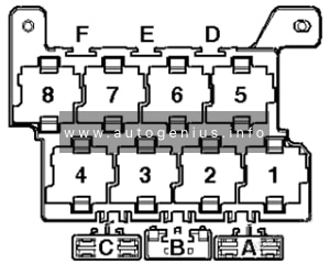
The 4th generation Kia Sportage was produced in 2016, 2017, 2018, 2019, 2020, 2021, 2022, 2023 with both gasoline and diesel engines. In this publication you will find a designation of the 4th generation Kia Sportage fuses and relays with boxes diagrams and their locations. Let’s highlight the fuse responsible for the cigarette lighter.

Instrument panel (driver’s side fuse panel)

Fuse box location

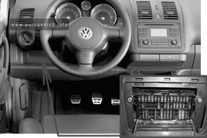
Located under the dashboard on the driver’s side behind the protective cover.

KIA Sportage (QL; 2017 - 2023) - fuse box location - passenger compartment
KIA Sportage (QL; 2017 – 2023) – fuse box location – passenger compartment


Fuse box diagram

Version 1
KIA Sportage (QL; 2017 - 2023) - fuse box diagram - passenger compartment (version 1)
KIA Sportage (QL; 2017 – 2023) – fuse box diagram – passenger compartment (version 1)


Version 2
KIA Sportage (QL; 2017 - 2023) - fuse box diagram - passenger compartment (version 2)
KIA Sportage (QL; 2017 – 2023) – fuse box diagram – passenger compartment (version 2)


Fuse name Ampere rating [A] Protected component
MDPS 7,5 MDPS Unit
MODULE 2 10 Headlamp LH/RH
SMART KEY 1 10 Smart Key Control Module/Immobilizer Module
A/BAG IND 7,5 Instrument Cluster
[Audio & Manual A/C] Hazard Switch
[Audio & Auto A/C] A/C Control Module
[Navigation] Center Facia Lamp
MODULE 4 10 Console Switch, Blind Spot Detection Radar LH/RH, AWD ECM, Crash Pad Switch, BCM, Lane Departure Warning Control Module
A/BAG 15 SRS Control Module
START 7,5 [W/O Smart Key & IMMO.] ICM Relay Box (Burglar Alarm Relay), Ignition Switch
[With Smart Key / IMMO.] Transaxle Range Switch, ECM, Smart Key Control Module
MODULE 3 10 Front/Rear Seat Warmer Control Module, ATM Shift Lever ILL., Front Air Ventilation Seat Control Module, A/V & Navigation Head Unit, Electro Chromic Mirror, Audio, A/C Control Module, Multipurpose Check Connector, Adaptive Front Lighting Module
CLUSTER 10 Instrument Cluster
MODULE 9 20 PCB Block (Fuse – ABS 3, VACUUM PUMP 2, ECU 6, AEB, TCU 2, MODULE)
HEATED
STEERING
15 BCM
MODULE 6 7,5 Front/Rear Seat Warmer Control Module, Front Air Ventilation Seat Control Module
MODULE 5 10 BCM, Smart Key Control Module
A/CON 2 7,5 A/C Control Module
MODULE 1 10 BCM, ATM Shift Lever
P/ WINDOW LH 25 Power Window Main Switch
A/CON 1 7,5 A/C Control Module, Cluster Ionizer, E/R Junction Block (Blower Relay)
WIPER RR 15 Rear Wiper Motor, ICM Relay Box (Rear Wiper Relay)
WASHER 15 Multifunction Switch
SMART KEY 3 10 [W/O Smart Key] Immobilizer Module
[With Smart Key] Smart Key Control Module, Start/Stop Button Switch
STOP LAMP 7,5 Smart Key Control Module, Stop Lamp Switch
P/ WINDOW RH 25 Power Window Main Switch, Passenger Power Window Switch
MEMORY 10 Wireless Charger, Instrument Cluster, Data Link Connector, BCM, ICM Relay Box (Outside Mirror
Folding/Unfolding Relay), Electro Chromic Mirror, A/C Control Module, Console Switch
SUN ROOF 1 20 Panorama Sunroof
TAIL GATE
OPEN
10 Tail Gate Relay
INTERIOR LAMP 10 Ignition Key Ill.& Door Warning Switch, Room Lamp, Overhead Console Lamp, Front Vanity Lamp LH/RH, Rear Personal Lamp LH/RH, Luggage Lamp, Glove Box Lamp
SMART KEY 2 15 Smart Key Control Module
MODULE 8 7,5 Key Solenoid
MULTI MEDIA 15 Audio, A/V & Navigation Head Unit, Rear USB Charger
S/HEATER
DRV/PASS
20 Front Seat Warmer Control Module, Front Air Ventilation Seat Control Module
SUN ROOF 2 20 Panorama Sunroof
P/SEAT (PASS) 30 Passenger Seat Manual Switch
POWER OUTLET 20 Front Power Outlet #1 (Front Cigarette Lighter)
S/HEATER
REAR
20 Rear Seat Warmer Control Module
DOOR LOCK 20 Door Lock/Unlock Relay
4WD 20 AWD ECM
MODULE 7 10 Hazard Switch, Driver/Passenger Smart Key Outside Handle, AEB Sensor
AMP 25 AMP
SAFETY
P/ WINDOW
25 Driver Safety Power Window Module
HEATED
MIRROR
10 Driver/Passenger Power Outside Mirror, A/C Control Module
P/SEAT (DRV) 30 Driver Seat Manual Switch
ACC 10 Rear USB Charger, AMP, Power Outside Mirror Switch, PCB Block(Power Outlet Relay), Smart Key Control Module, Audio, A/V & Navigation Head Unit, BCM, Wireless Charger

Engine compartment fuse panel

Fuse box location

Located on the left side of the engine compartment.

KIA Sportage (QL; 2017 - 2023) - fuse box location - engine compartment
KIA Sportage (QL; 2017 – 2023) – fuse box location – engine compartment


Fuse box diagram

Version 1
KIA Sportage (QL; 2017 - 2023) - fuse box diagram - engine compartment (version 1)
KIA Sportage (QL; 2017 – 2023) – fuse box diagram – engine compartment (version 1)


Version 2
KIA Sportage (QL; 2017 - 2023) - fuse box diagram - engine compartment (version 2)
KIA Sportage (QL; 2017 – 2023) – fuse box diagram – engine compartment (version 2)


Fuse name Ampere rating [A] Protected component
MULTI FUSE COOLING FAN 2 80 Cooling Fan Motor
MDPS 80 MDPS Unit
B+ 1 60 Smart Junction Block (IPS 2 (5CH), IPS 3 (2CH), IPS 4 (2CH), IPS 5 (2CH), IPS 6 (1CH), Fuse – AMP)
B+ 2 60 Smart Junction Block (IPS 1 (5CH), Fuse – MODULE 7, SMART KEY 2, SMART KET 3, MODULE 8, STOP LAMP)
B+ 3 50 Smart Junction Block (Fuse – SUNROOF 1, SUNROOF 2, S/HEATER DRV/PASS, S/HEATER REAR, SAFETY P/WINDOW, Power Window Relay
BLOWER 40 Blower Relay
REAR HEATED 40 Rear Heated Relay
IG1 40 [W/O Smart Key] Ignition Switch, [With Smart Key] PCB Block (PDM (IG1)/PDM (ACC) Relay)
IG2 30 Start Relay, [W/O Smart Key] Ignition Switch, [With Smart Key] PCB Block (PDM (IG2) Relay)
FUSE B+ 4 50 Smart Junction Block (Fuse – AWD, P/SEAT (DRV), P/SEAT (PASS), TAIL GATE OPEN, DOOR LOCK, Leak Current Autocut Device Relay)
COOLING FAN 1 50 Cooling Fan 1 Relay
ABS 1 40 ESC Control Module, Multipurpose Check Connector
POWER
TAIL GATE
40 Power Tail Gate Module
ABS 2 40 ESC Module
COOLING FAN 3 40 Cooling Fan 1 Relay
E-CVVT 1 20 PCM
E-CVVT 2 20 PCM
WIPER FRT 1 30 [W/O Smart Key] Ignition Switch, [With Smart Key] PDM (IG2) Relay
TCU 1 15 PCM
WIPER FRT 2 10 BCM, PCM
ECU 3 20 PCM
HORN 15 A Horn Relay
BATTERY
MANAGEMENT
10 Battery Sensor
SENSOR 2 10 Fuel Pump Relay, Oil Control Valve, Purge Control Solenoid Valve, Variable Intake Solenoid Valve, RCV Control Solenoid Valve
SENSOR 1 15 Oxygen Sensor (Up/Down)
ECU 2 20 Ignition Coil #1/#2/#3/#4
ECU 4 15 PCM
SENSOR 3 10 E/R Junction Block (Cooling Fan 1 Relay), Canister Close Valve
FUEL PUMP 20 Fuel Pump Relay
AEB 10 AEB Sensor
MODULE 7,5 Stop Lamp Switch
B/ALARM
HORN
10 E/R Junction Block (B/Alarm Horn Relay)
H/LAMP HI 10 BI-Function H/LP Relay
ABS 3 10 ESC Module
POWER
OUTLET 1
20 Front Power Outlet #2
ECU 6 10 PCM
TCU 2 15 Transaxle Range Switch
B/UP LAMP 10 Rear Bumper Lamp LH/RH, Electro Chromic Mirror
POWER
OUTLET 2
20 Rear Power Outlet
ECU 1 30 Engine Control Relay
DEICER 15 E/R Junction Block (Deicer Relay)
VACUUM
PUMP 1
20 Vacuum Pump
VACUUM
PUMP 2
15 Vacuum Pump, Cooling Fan Motor, Vacuum Switch


Relay

Relay name Type
Cooling Fan 1 Relay MINI
Rear Defogger Relay MICRO
B/A Horn Relay MICRO
Deicer Relay MICRO
Cooling Fan 2 Relay MICRO
Start Relay MICRO
Blower Relay MICRO


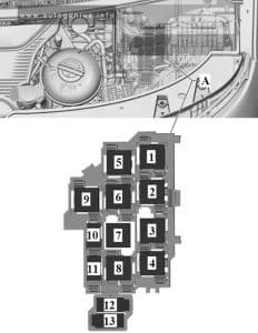
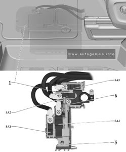
Engine compartment fuse panel (Battery terminal cover)

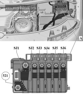
On the positive terminal of the storage battery there is a high-power main power fuse made in the form of a fusible link.

KIA Sportage (QL; 2017 - 2023) - fuse box diagram - engine compartment (battery terminal cover)
KIA Sportage (QL; 2017 – 2023) – fuse box diagram – engine compartment (battery terminal cover)

WARNING: Terminal and harness assignments for individual connectors will vary depending on vehicle equipment level, model, and market.
RAM Cargo Van (2012 – 2015) – fuse and relay box diagram

RAM Cargo Van (2012 – 2015) – fuse and relay box diagram

Year of production: 2012, 2013, 2014, 2015


The Ram Cargo Van (2012–2015), also known as the Ram C/V Tradesman, was a commercial cargo vehicle based on the Dodge Grand Caravan platform. It was designed to serve businesses and tradespeople who needed a versatile, cost-effective solution for carrying equipment, goods, and materials. Chrysler introduced the Ram Cargo Van as part of the Ram commercial vehicle lineup after it split off Ram Trucks from the Dodge brand. The Ram C/V Tradesman was essentially a converted minivan with its interior reconfigured for commercial use, combining the utility of a cargo van with the drivability of a minivan.


This article covers the Ram Cargo Van (C/V Tradesman), produced between 2012 and 2015. It includes fuse box diagrams for the 2012, 2013, 2014, and 2015 models, along with information on the location of the fuse panels within the vehicle and details on the function of each fuse (fuse layout).


Totally Integrated Power Module

Fuse Box Location

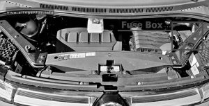
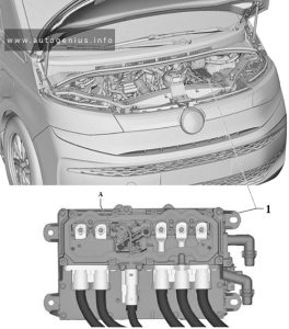
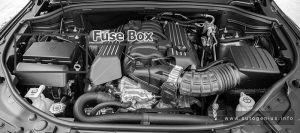
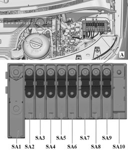
The Totally Integrated Power Module is located in the engine compartment near the battery.

RAM Cargo Van - fuse and relay box location - engine compartment
RAM Cargo Van – fuse and relay box location – engine compartment


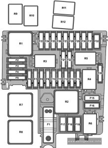
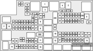
Fuse Box Diagram

RAM Cargo Van - fuse and relay box diagram - engine compartment
RAM Cargo Van – fuse and relay box diagram – engine compartment


Power windows:
  • 2012: The power windows are fused by a 25 Amp circuit breaker located under the instrument panel near the steering column.
  • 2013-2015: The power windows are fused by a 25 Amp circuit breaker located in the Totally Integrated Power Module.

Assignment of the fuses in the engine compartment

Cavity Cartridge fuse Micro Fuse Description
J1 40 Power Folding Seat
J2 30 Power Liftgate Module
J3 30 Rear Door Module
J4 25 Driver Door Node
J5 25 Passenger Door Node
J6 40 Antilock Brakes Pump/Stability Control System
J7 30 Antilock Brakes Valve/Stability Control System
J8 40 Power Memory Seat – If Equipped
J9 40 Partial Zero Emissions Vehicle Motor/Flex Fuel – If Equipped
J10 30 Headlamp Wash/Manifold Tuning Valve – If Equipped
J11 30 Power Sliding Door Module/Anti–Theft Module – If Equipped
J12 30 HVAC Rear Blower, Radiator Fan Motor
J13 60 Ignition Off Draw (IOD) – Main
J14 40 Rear Window Defogger
J15 40 Front Blower
J17 40 Starter Solenoid
J18 20 Powertrain Control Module Trans Range
J19 60 Radiator Fan
J20 30 Front Wiper LO/HI
J21 20 Front/Rear Washer
J22 25 Sunroof Module
M1 15 Rear Center Brake Lamp/Brake Switch
M2 20 Front Fog Lamps
M3 20 Front/Rear Axle Locker, Vacuum Pump Motor
M4 10 Trailer Tow
M5 25 Inverter
M6 20 Power Outlet #1 (ACC), Rain Sensor, Cigar Lighter (Instrument Panel or with Console Rear)
M7 20 Power Outlet #2 (BATT/ACC SELECT) – Center Seat or with Console Rear
M8 20 Front Heated Seat – If Equipped
M9 20 Rear Heated Seat – If Equipped
M10 15 Ignition Off Draw — Video System, Satellite Radio, DVD, Hands-Free Module, Universal Garage Door Opener, Vanity Lamp, Streaming Video Module – If Equipped
M11 10 Climate Control System
M12 30 Amplifier/Radio
M13 20 Instrument Cluster, SIREN, Clock Module, Multi-Function Control Switch – If Equipped
M14 20 Trailer Tow – If Equipped
M15 20 Rear View Mirror, Instrument Cluster, Multi-Function Control Switch, Tire Pressure Monitor, Glow Plug Module – If Equipped
M16 10 Airbag Module/Occupant Classification Module
M17 15 Left Tail/License/Park Lamp, Running Lamps
M18 15 Right Tail/Park/Run Lamp
M19 25 Powertrain
M20 15 Instrument Cluster Interior Light, Switch Bank, Steering Column Module, Switch Steering Wheel
M21 20 Powertrain
M22 10 Horn
M23 10 Horn
M24 25 Rear Wiper
M25 20 Fuel Pump, Diesel Lift Pump – If Equipped
M26 10 Power Mirror Switch, Driver Window Switch
M27 10 Wireless Control Module, Keyless Entry Module
M28 10 Powertrain, Transmission Control Module
M29 10 Occupant Classification Module
M30 15 Rear Wiper Module, Power Folding Mirror
M31 20 Back-Up Lamps
M32 10 Airbag Module, THATCHUM – If Equipped
M33 10 Powertrain
M34 10 Park Assist, Heater Climate Control Module, Headlamp Wash, Compass, Rear Camera, Door Lamps, Flashlight, Relay Diesel Cabin Heater, Rad Fan Diesel – If Equipped
M35 10 Heated Mirrors
M36 20 Power Outlet #3 (Instrument Panel or with Console Center)
M37 10 Antilock Brakes, Stability Control, Stop Lamp, Fuel Pump
M38 25 Door Lock/Unlock Motors, Liftgate Lock/Unlock Motors
CB1 25A circuit breaker 2013-2015: Power Windows

WARNING: Terminal and harness assignments for individual connectors will vary depending on vehicle equipment level, model, and market.
RAM 5500 Chassis Cab (2015 – 2017) – fuse and relay box diagram

RAM 5500 Chassis Cab (2015 – 2017) – fuse and relay box diagram

Year of production: 2015, 2016, 2017

The Ram 5500 Chassis Cab (2016-2017) is a highly capable heavy-duty truck designed for commercial applications that require serious towing, payload, and customization options. Positioned as the most powerful and durable model in the Ram Chassis Cab lineup, the 5500 is ideal for industries like construction, towing, and utility services, where strength and versatility are essential. It is known for its powerful engine options, robust towing capabilities, and the ability to be upfitted for various roles.


Power Distribution Center

Fuse box location

The Power Distribution Center is located in the engine compartment near the battery.

RAM 5500 Chassis Cab - fuse and relay box location - engine compartment
RAM 5500 Chassis Cab – fuse and relay box location – engine compartment


Fuse box diagram

RAM 5500 Chassis Cab - fuse and relay box diagram - engine compartment
RAM 5500 Chassis Cab – fuse and relay box diagram – engine compartment


Assignment of the fuses in the engine compartment (2015-2017)

Cartridge Fuse Mini Fuse Description
F01 80A Red/Black Rad Fan Control Module – If Equipped
F03 60A Yellow Rad Fan – If Equipped
F05 40A Green Compressor for Air Suspension – If Equipped
F06 40A Green Antilock Brakes / Electronic Stability Control Pump
F07 40A Green Starter Solenoid
F08 30A Pink / 20A Blue Emissions Diesel – If Equipped
F09 40A Green Diesel Fuel Heater – If Equipped
F10 40A Green / 50A Red (with Stop/Start) Body Controller / Exterior Lighting #2
F11 30A Pink Integrated Trailer Brake Module – If Equipped
F12 40A Green 2013-2015: Body Controller #3 / Interior Lights
2016-2017: Body Controller #3 / Power Locks
F13 40A Green Blower Motor
F14 40A Green 2013-2015: Body Controller #4 / Power Locks
2016-2017: Body Controller #4 / Interior Lighting
F15 30A Pink 2013-2014: Electric Park Brake Right Side – If equipped
F16 30A Pink 2015-2017: Smart Bar – If Equipped
F19 20A Blue (1500 LD Diesel)
30A Pink (Cummins Diesel)
SCR – If Equipped
F20 30A Pink Passenger Door Module
F21 30A Pink Drive Train Control Module
F22 20A Yellow / 20A Blue / 30A Pink (Cummins Diesel) Engine Control Module
F23 30A Pink 2013-2015: Body Controller #1
2016-2017: Body Controller #1 / Interior Lighting
F24 30A Pink Driver Door Module
F25 30A Pink Front Wiper
F26 30A Pink Antilock Brakes / Stability Control Module / Valves
F28 20A Blue Trailer Tow Backup Lights – If Equipped
F29 20A Blue Trailer Tow Parking Lights – If Equipped
F30 30A Pink Trailer Tow Receptacle
F31 30A Pink (1500 LD Diesel) 2015-2017: Urea Heater Control – If Equipped
F32 30A Pink 2013-2015: Drive Train Control Module – If equipped
2016-2017: Spare Fuse
F33 20A Yellow / 20A Blue 2013-2014: Diesel Fuel Heater #1 – If Equipped / Rear Blower – If equipped
2015-2017: Special Services Vehicle Only
F34 30A Pink Vehicle System Interface Module #2 – If Equipped
F35 30A Pink Sunroof – If Equipped
F36 30A Pink Rear Defroster – If Equipped
F37 30A Pink Cummins Diesel Fuel Heater #2 – If Equipped
F38 30A Pink Power Inverter 115V AC – If Equipped
F39 30A Pink / 20A Blue 2013-2015: Vehicle System Interface Module #1 – If equipped
2016-2017: Power Outlet – Special Services Only
F41 10A Red Active Grill Shutter – If Equipped
F42 20A Yellow Horn
F43 10A Red 2013-2014: Snow Plow (Left) – If Equipped
F44 10A Red Diagnostic Port
F46 10A Red 2013-2015: Tire Pressure Monitor
2016-2017: Upfitter – If Equipped
F47 10A Red 2013-2014: Snow Plow (Right) – If Equipped
F49 10A Red Instrument Panel Cluster (Except Fleet Vehicles)
F50 20A Yellow Air Suspension Control Module – If Equipped
F51 10A Red 2013-2015: Ignition Node Module / Keyless Ignition
2016-2017: Ignition Node Module / Keyless Ignition (Instrument Panel Cluster – Fleet Vehicles Only)
F52 5A Tan Battery Sensor
F53 20A Yellow Trailer Tow – Left Turn/Stop Lights
F54 20A Yellow Adjustable Pedals
F55 20A Yellow 2013-2014: E38 Radio – If equipped
F56 15A Blue Additional Diesel Content – If Equipped
F57 20A Yellow Transmission
F58 20A Yellow (Gas Engine) / 25A Natural (Diesel Engine) 2013-2014: Engine Cooling Pump
2015-2017: Spare Fuse
F59 10A Red 2015-2017: SCR Relay – If Equipped
F60 15A Blue Underhood Lamp
F61 20A Yellow / 10A Red (1500 LD Diesel & Cummins Diesel) 2013-2014: Power Take-off Unit – If Equipped
2015-2017: PM Sensor – If Equipped
F62 10A Red Air Conditioning Clutch
F63 20A Yellow Ignition Coils (Gas), Urea Heater (Cummins Diesel)
F64 25A Clear Fuel Injectors / Powertrain
F65 10A Red 2013-2015: USB interface
2016-2017: Spare Fuse
F66 10A Red Sunroof / Passenger Window Switches / Rain Sensor
F67 10A Red CD / DVD / Bluetooth Hands-free Module -If Equipped
F69 15A Blue Mod SCR 12V (Cummins Diesel) – If Equipped
F70 30A Green Fuel Pump Motor
F71 25A Clear Amplifier
F72 10A Red 2013-2015: Voltage Stabilizer Modules – If equipped
2016-2017: PCM – If Equipped
F73 20A Yellow 2015-2017: Fuel Transfer Pump (HD Only) – If Equipped
F74 20A Yellow / 10A Red Brake Vacuum Pump Gas/Diesel – If Equipped
F75 10A Red Coolant Temperature Valve Actuator
F76 10A Red Antilock Brakes / Electronic Stability Control
F77 10A Red Drivetrain Control Module / Front Axle Disconnect Module
F78 10A Red Engine Control Module / Electric Power Steering
F79 15A Blue Clearance Lights
F80 10A Red Universal Garage Door Opener / Compass
F81 20A Yellow Trailer Tow Right Turn/Stop Lights
F82 10A Red Steering Column Control Module / Cruise Control
F84 15A Blue Switch Bank / Instrument Cluster
F85 10A Red Airbag Module
F86 10A Red Airbag Module
F87 10A Red Air Suspension – If Equipped / Trailer Tow / Steering Column Control Module
F88 15A Blue Instrument Panel Cluster
F90 / F91 20A Yellow Power Outlet (Rear Seats) Customer Selectable
F93 20A Yellow Cigar Lighter
F94 10A Red Shifter / Transfer Case Module
F95 10A Red Rear Camera / Park Assist
F96 10A Red Rear Seat Heater Switch
F97 25A Clear Rear Heated Seats & Heated Steering Wheel – If Equipped
F98 25A Clear Front Heated Seats – If Equipped
F99 10A Red Climate Control
F100 10A Red 2015-2017: Upfitters – If Equipped
F101 15A Blue Electrochromatic Mirror / Smart High Beams – If Equipped
F104 20A Yellow Power Outlets (Instrument Panel / Center Console)
F104 20 Power Outlets (Instrument Panel/Center Console)

WARNING: Terminal and harness assignments for individual connectors will vary depending on vehicle equipment level, model, and market.
RAM 5500 Chassis Cab (2013 – 2015) – fuse and relay box diagram

RAM 5500 Chassis Cab (2013 – 2015) – fuse and relay box diagram

Year of production: 2013, 2014, 2015


The Ram 5500 Chassis Cab (2013-2015) is a top-tier heavy-duty commercial truck designed for demanding tasks that require maximum power, towing, and payload capabilities. As the largest model in the Ram Chassis Cab lineup, it offers exceptional strength and versatility, making it ideal for various industries such as construction, towing, and custom upfit needs. Built for reliability and durability, the Ram 5500 is well-suited for heavy-duty applications.


Power Distribution Center

Fuse box location

The Power Distribution Center is located in the engine compartment near the battery.

RAM 5500 Chassis Cab - fuse and relay box location - engine compartment
RAM 5500 Chassis Cab – fuse and relay box location – engine compartment


Fuse box diagram

RAM 5500 Chassis Cab - fuse and relay box diagram - engine compartment
RAM 5500 Chassis Cab – fuse and relay box diagram – engine compartment


Assignment of the fuses in the engine compartment (2013-2015)

Cavity Cartridge fuse Micro Fuse Description
F01 80 Rad Fan Control Module – If equipped
F03 60 Rad Fan – If Equipped
F05 40 Compressor for Air Suspension – If Equipped
F06 40 Antilock Brakes/Electronic Stability Control Pump
F07 40 Starter Solenoid
F08 30 Emissions Diesel – If Equipped
F09 40 Diesel Fuel Heater – If Equipped
F10 40 Body Controller / Exterior Lighting #2
50 Body Controller / Exterior Lighting #2 – If Equipped with Stop/Start
F11 30 Integrated Trailer Brake Module – If Equipped
F12 40 Body Controller #3 / Interior Lights
F13 40 Blower Motor
F14 40 Body Controller #4 / Power Locks
F15 30 Electric Park Brake Right Side – If Equipped
F19 30 SCR – If Equipped
F20 30 Passenger Door Module
F21 30 Drive Train Control Module
F22 20 Engine Control Module
F23 30 Body Controller #1
F24 30 Driver Door Module
F25 30 Front Wiper Low Speed
30 Front Wiper High Speed
F26 30 Antilock Brakes/Stability Control Module/Valves
F28 20 Trailer Tow Backup Lights – If Equipped
F29 20 Trailer Tow Parking Lights – If Equipped
F30 30 Trailer Tow Receptacle
F32 30 Drive Train Control Module – If Equipped
F33 20 Diesel Fuel Heater #1 – If Equipped /Rear Blower – If Equipped
F34 30 Vehicle System Interface Module #2 – If Equipped
F35 30 Sunroof – If Equipped
F36 30 Rear Defroster– If Equipped
F37 30 Diesel Fuel Heater #2 if equipped
F38 30 Power Inverter 115V AC– If Equipped
F39 30 Vehicle System Interface Module #1– If Equipped
F41 10 Active Grill Shutter
F42 20 Horn
F43 10 Snow Plow (Left) – If Equipped
F44 10 Diagnostic Port
F46 10 Tire Pressure Monitor
F47 10 Snow Plow (Right) – If Equipped
F49 10 Instrument Panel Cluster
F50 20 Air Suspension Control Module – If Equipped
F51 10 Ignition Node Module / Keyless Ignition
F52 5 Battery Sensor
F53 20 Trailer Tow – Left Turn/Stop Lights
F54 20 Adjustable Pedals
F55 20 E38 Radio – If Equipped
F56 15 Additional Diesel Content – If Equipped
F57 20 Transmission
F58 20 (Gas engine) Engine Cooling Pump
25 (Diesel engine)
F60 15 Underhood Lamp
F61 20 Power Take-off Unit – If Equipped
F62 10 Air Conditioning Clutch
F63 20 IgnitionCoils (Gas), Urea Heater (Diesel)
F64 25 Fuel Injectors / Powertrain
F65 10 USB interface
F66 10 Sunroof / Passenger Window Switches /Rain Sensor
F67 10 CD / DVD / Bluetooth Hands-free Module – If Equipped
F69 15 Mod SCR 12V – If Equipped
F70 30 Fuel Pump Motor
F71 25 Amplifier
F72 10 Voltage Stabilizer Modules – If Equipped
F74 20 (Gas engine) Brake Vacuum Pump Gas/Diesel – If Equipped
10 (Diesel engine)
F75 10 Coolant Temperature Valve Actuator
F76 10 Antilock Brakes/Electronic Stability Control
F77 10 Drivetrain Control Module/Front Axle Disconnect Module
F78 10 Engine Control Module / Electric Power Steering
F79 15 Clearance Lights
F80 10 Universal Garage Door Opener / Compass
F81 20 Trailer Tow Right Turn/Stop Lights
F82 10 Steering Column Control Module/ Cruise Control
F84 15 Switch Bank/Instrument Cluster
F85 10 Airbag Module
F86 10 Airbag Module
F87 10 Air Suspension-If Equipped / Trailer Tow / Steering Column Control Module
F88 15 Instrument Panel Cluster
F90 20 Power Outlet (Rear seats) Customer Selectable
F91
F93 20 Cigar Lighter
F94 10 Shifter / Transfer Case Module
F95 10 Rear Camera / Park Assist
F96 10 Rear Seat Heater Switch
F97 25 Rear Heated Seats & Heated Steering Wheel – If Equipped
F98 25 Front Heated Seats – If Equipped
F99 10 Climate Control
F101 15 Electrochromatic Mirror / Smart High Beams – If Equipped
F104 20 Power Outlets (Instrument Panel/Center Console)

WARNING: Terminal and harness assignments for individual connectors will vary depending on vehicle equipment level, model, and market.
RAM 5500 Chassis Cab (2012) – fuse box diagram

RAM 5500 Chassis Cab (2012) – fuse box diagram

Year of production: 2012


The 2012 Ram 5500 Chassis Cab is a heavy-duty truck designed for the most demanding commercial tasks. It sits at the top of Ram’s Chassis Cab lineup, offering impressive power, durability, and versatility for various applications like towing, hauling, and upfitting for custom uses. Built for businesses in industries such as construction, towing, and transportation, the Ram 5500 is designed to handle extreme payloads and heavy-duty towing with ease.


Totally Integrated Power Module (TIPM)

Fuse box location

The totally integrated power module (TIPM) is located in the engine compartment near the battery

RAM 5500 Chassis Cab - fuse and relay box location - engine compartment
RAM 5500 Chassis Cab – fuse and relay box location – engine compartment


Fuse box diagram

RAM 5500 Chassis Cab - fuse and relay box diagram - engine compartment
RAM 5500 Chassis Cab – fuse and relay box diagram – engine compartment


Assignment of the fuses in the engine compartment (2012)

Cavity Cartridge fuse Micro Fuse Description
J01 40 Trailer Tow
J02 30 Electric Brake
J03 30 Diesel Powertrain Control Module – If Equipped
J04 25 Driver Door Node
J05 25 Passenger Door Node
J06 40 Antilock Brakes Pump/Stability Control System
J07 30 Antilock Brakes Valve/Stability Control System
J08 40 Power Seat
J09 30 Sway Bar Module – If Equipped
J10 30 Transfer Case Module
J11 30 Rear Defroster
J12 60 Main Ignition Off Draw (IOD) Fuse
J13 20 Trailer Tow Lamps/Park Lamps
J14 40 Front Blower
J17 40 Starter Motor Solenoid
J18 20 Powertrain Control Module Transmission Range
J19 60 Rad Fan Motor HI/Rad Fan Motor Low
J20 30 Front Wiper Ground/Low/High
J21 20 Washer Control
J22 25 Sunroof Module
M1 15 Stop Switch Lamp
M5 25 115V AC Inverter
M6 20 Power Outlet (Instrument Panel or Front Console)/Rain Snsr
M7 20 Power Outlet (Rear Console or Center Seat)
M8 20 Front Heated Seat & Steering Wheel
M9 20 Rear Heated Seats
M10 15 Hands Free Module/Vanity Lamp/Universal Garage Door Opener Module
M11 10 Climate Control System
M12 30 Radio/Amplifier
M13 20 Main #2 Instrument Cluster/Wireless Control Module/ITM/Siren/Multifunction Switch (Steering Column Module)
M14 20 Back Up Camera (Domestic Only)
M15 20 Power Seat Module(s)/Audio Telematics/Daytime Running Lights Relay/Instrument Cluster/Transfer Case Module
M16 10 Airbag Module
M18 15 Center Stop Lamp
M19 25 Automatic Shutdown 1 and 2
M20 15 Instrument Cluster Interior Lighting /Sw Steering Wheel/Sw Bank
M21 20 Automatic Shutdown 3
M22 10 Horns (Low/High) – Righ
M23 10 Horns (Low/High) – Left
M25 20 Fuel Pump Motor/Diesel Lift Pump – If Equipped
M26 10 Driver’s Door Switch
M27 10 Ignition Switch
M28 15 Powertrain Control Module
M29 10 Tire Pressure Monitor
M30 15 J1962 Diag Connector
M31 20 Back-Up Lamps
M32 10 Airbag Module
M33 10 Powertrain Control Module
M34 10 Park Assist Module/Climate Control System Module/IR Sensor/Compass Module
M35 15 Left Front & Rear Parklamps
M36 20 Power Outlet (Instrument Panel or Center Console)
M37 10 Antilock Brakes/Stability Control System Module/Stoplamp Switch
M38 25 All Door Lock &Unlock

WARNING: Terminal and harness assignments for individual connectors will vary depending on vehicle equipment level, model, and market.
RAM 5500 Chassis Cab (2011) – fuse and relay box diagram

RAM 5500 Chassis Cab (2011) – fuse and relay  box diagram

Year of production: 2011


The Ram 5500 Chassis Cab (2011) is the most heavy-duty truck in the Ram Chassis Cab lineup for that year, offering exceptional towing and payload capacities for demanding commercial applications. It is designed to be upfitted for various roles, including tow trucks, dump trucks, flatbeds, and other specialized commercial uses. The 2011 Ram 5500 is ideal for businesses that require a reliable, durable, and powerful vehicle capable of handling extreme loads and rough work environments.


Totally Integrated Power Module (TIPM)

Fuse box location

The totally integrated power module (TIPM) is located in the engine compartment near the battery

RAM 5500 Chassis Cab  - fuse and relay box location - engine compartment
RAM 5500 Chassis Cab – fuse and relay box location – engine compartment


Fuse box diagram

RAM 5500 Chassis Cab  - fuse and relay box diagram - engine compartment
RAM 5500 Chassis Cab – fuse and relay box diagram – engine compartment


Assignment of the fuses in the engine compartment (2011)

Cavity Cartridge fuse Micro Fuse Description
J01 30 Bat – Presafe #1/CM2200
J02 30 Bat – Trailer Tow Main
J03 25 Bat – Passenger Door Node
J04 40 Bat – ABS Pump
J05 30 Bat – ABS Valve
J06 30 Bat – H/Lamp Wash/MTV/CM2200/Elec Vac Pump
J07 25 Bat – Driver Door Node
J08 30 Bat – DTCM/Axle Locks
J09 30 Bat – Plg/Electric Brake
J10 40 Bat – L/Bar/Off-Road
J11 30 Bat – Sway/Thatchum/Rear Doors
J12 40 Starter Solenoid
J13 60 Bat – Rad Fan #1/#2/SSR
J14 40 Bat – Folding Seat/PZEV
J15 60 Bat – IOD Main
J16 40 Frt HVAC Motor
M17 25 Bat – Sunroof/Skylight
M18 25 TCM/Trans Range
M19 5 Ign R/ACC – Sunroof/Window Sw Illum
M20 25 Frt Wiper
M21 25 Door Locks
M22 20 Fuel Pump
M23 20 Bat – Trlr Light/Pre-Safe #2
M24 20 Bat – Trlr Tow BUX/HGM
M25 10 Bat – J1962 Diag/Mirrors
M26 10 Bat – Ign Sw, WIN, PASS
M27 15 Bat – CHMSL/Brake Sw
M28 10 Bat – Corax TPM/PEM/HVAC Htr Pump
M29 15 Bat – Folding Mirror
M30 25 Bat – Inverter
M31 20 Bat – Pwr Out #1
M32 20 Fr/Rr Washer
M33 15 Bat – NGC/EATX/PCM
M34 15 Bat – CCN/Interior Light/SCM/Sw Bank
M35 20 Ign R-Frt Seat/Vent
M36 20 Ign R-Rear Seat/Steer Wheel
M37 10 Horn #1
M38 20 IOD-CCN/Interior Mods
M39 30 IOD-Amp/Radio
M40 25 Rear Wiper
M41 15 IOD-SDARS/VES2–3/DVD/HFM/UGDO/Vanity Lamp
M42 10 IOD-HVAC, U/Hood Lamp
M43 10 Horn #2
M44 10 IGN R/S-ORC/OCM
M45 10 IGN R-ORC/Trail Tow (BUX) Sense
M46 20 IGN R-Trail Tow (BUX)
M47 10 IGN R-H/Lamp Wash/HVAC/Park Assist/Ir Sns
M48 20 IGN R/ACC-Pwr Outlet #2
M49 20 IGN R/ACC/Bat-Pwr Outlet #3
M50 25 ASD #1, #2
M51 20 ASD #3
M52 10 IGN R/S-SWAY/TCASE/DTCM/FAD
M53 15 IGN R/S-MFSW/CNN/SCM/TPM/RR View
M54 20 IOD – Spare

WARNING: Terminal and harness assignments for individual connectors will vary depending on vehicle equipment level, model, and market.
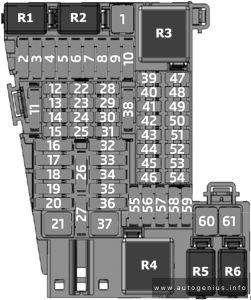
RAM 4500 (2015 – 2017) – fuse and relay box diagram

RAM 4500 (2015 – 2017) – fuse and relay box diagram

Year of production: 2015, 2016, 2017


The Ram 4500 Chassis Cab (2015-2017) is a heavy-duty commercial vehicle built to handle demanding tasks such as towing, hauling, and upfitting for various industries, including construction, utility services, and towing. Positioned between the Ram 3500 and the more heavy-duty Ram 5500, the Ram 4500 offers a balance of power and versatility while still providing excellent performance for commercial-grade work.


Power Distribution Center

Fuse box  location

The Power Distribution Center is located in the engine compartment near the battery.

RAM 4500 - fuse and relay box location - engine compartment
RAM 4500 – fuse and relay box location – engine compartment


Fuse box diagram


Assignment of the fuses in the engine compartment (2015-2017)

Cartridge Fuse Mini Fuse Description
F01 80A Red/Black Rad Fan Control Module – If Equipped
F03 60A Yellow Rad Fan – If Equipped
F05 40A Green Compressor for Air Suspension – If Equipped
F06 40A Green Antilock Brakes / Electronic Stability Control Pump
F07 40A Green Starter Solenoid
F08 30A Pink / 20A Blue Emissions Diesel – If Equipped
F09 40A Green Diesel Fuel Heater – If Equipped
F10 40A Green / 50A Red (with Stop/Start) Body Controller / Exterior Lighting #2
F11 30A Pink Integrated Trailer Brake Module – If Equipped
F12 40A Green 2013-2015: Body Controller #3 / Interior Lights
2016-2017: Body Controller #3 / Power Locks
F13 40A Green Blower Motor
F14 40A Green 2013-2015: Body Controller #4 / Power Locks
2016-2017: Body Controller #4 / Interior Lighting
F15 30A Pink 2013-2014: Electric Park Brake Right Side – If equipped
F16 30A Pink 2015-2017: Smart Bar – If Equipped
F19 20A Blue (1500 LD Diesel)
30A Pink (Cummins Diesel)
SCR – If Equipped
F20 30A Pink Passenger Door Module
F21 30A Pink Drive Train Control Module
F22 20A Yellow / 20A Blue / 30A Pink (Cummins Diesel) Engine Control Module
F23 30A Pink 2013-2015: Body Controller #1
2016-2017: Body Controller #1 / Interior Lighting
F24 30A Pink Driver Door Module
F25 30A Pink Front Wiper
F26 30A Pink Antilock Brakes / Stability Control Module / Valves
F28 20A Blue Trailer Tow Backup Lights – If Equipped
F29 20A Blue Trailer Tow Parking Lights – If Equipped
F30 30A Pink Trailer Tow Receptacle
F31 30A Pink (1500 LD Diesel) 2015-2017: Urea Heater Control – If Equipped
F32 30A Pink 2013-2015: Drive Train Control Module – If equipped
2016-2017: Spare Fuse
F33 20A Yellow / 20A Blue 2013-2014: Diesel Fuel Heater #1 – If Equipped / Rear Blower – If equipped
2015-2017: Special Services Vehicle Only
F34 30A Pink Vehicle System Interface Module #2 – If Equipped
F35 30A Pink Sunroof – If Equipped
F36 30A Pink Rear Defroster – If Equipped
F37 30A Pink Cummins Diesel Fuel Heater #2 – If Equipped
F38 30A Pink Power Inverter 115V AC – If Equipped
F39 30A Pink / 20A Blue 2013-2015: Vehicle System Interface Module #1 – If equipped
2016-2017: Power Outlet – Special Services Only
F41 10A Red Active Grill Shutter – If Equipped
F42 20A Yellow Horn
F43 10A Red 2013-2014: Snow Plow (Left) – If Equipped
F44 10A Red Diagnostic Port
F46 10A Red 2013-2015: Tire Pressure Monitor
2016-2017: Upfitter – If Equipped
F47 10A Red 2013-2014: Snow Plow (Right) – If Equipped
F49 10A Red Instrument Panel Cluster (Except Fleet Vehicles)
F50 20A Yellow Air Suspension Control Module – If Equipped
F51 10A Red 2013-2015: Ignition Node Module / Keyless Ignition
2016-2017: Ignition Node Module / Keyless Ignition (Instrument Panel Cluster – Fleet Vehicles Only)
F52 5A Tan Battery Sensor
F53 20A Yellow Trailer Tow – Left Turn/Stop Lights
F54 20A Yellow Adjustable Pedals
F55 20A Yellow 2013-2014: E38 Radio – If equipped
F56 15A Blue Additional Diesel Content – If Equipped
F57 20A Yellow Transmission
F58 20A Yellow (Gas Engine) / 25A Natural (Diesel Engine) 2013-2014: Engine Cooling Pump
2015-2017: Spare Fuse
F59 10A Red 2015-2017: SCR Relay – If Equipped
F60 15A Blue Underhood Lamp
F61 20A Yellow / 10A Red (1500 LD Diesel & Cummins Diesel) 2013-2014: Power Take-off Unit – If Equipped
2015-2017: PM Sensor – If Equipped
F62 10A Red Air Conditioning Clutch
F63 20A Yellow Ignition Coils (Gas), Urea Heater (Cummins Diesel)
F64 25A Clear Fuel Injectors / Powertrain
F65 10A Red 2013-2015: USB interface
2016-2017: Spare Fuse
F66 10A Red Sunroof / Passenger Window Switches / Rain Sensor
F67 10A Red CD / DVD / Bluetooth Hands-free Module -If Equipped
F69 15A Blue Mod SCR 12V (Cummins Diesel) – If Equipped
F70 30A Green Fuel Pump Motor
F71 25A Clear Amplifier
F72 10A Red 2013-2015: Voltage Stabilizer Modules – If equipped
2016-2017: PCM – If Equipped
F73 20A Yellow 2015-2017: Fuel Transfer Pump (HD Only) – If Equipped
F74 20A Yellow / 10A Red Brake Vacuum Pump Gas/Diesel – If Equipped
F75 10A Red Coolant Temperature Valve Actuator
F76 10A Red Antilock Brakes / Electronic Stability Control
F77 10A Red Drivetrain Control Module / Front Axle Disconnect Module
F78 10A Red Engine Control Module / Electric Power Steering
F79 15A Blue Clearance Lights
F80 10A Red Universal Garage Door Opener / Compass
F81 20A Yellow Trailer Tow Right Turn/Stop Lights
F82 10A Red Steering Column Control Module / Cruise Control
F84 15A Blue Switch Bank / Instrument Cluster
F85 10A Red Airbag Module
F86 10A Red Airbag Module
F87 10A Red Air Suspension – If Equipped / Trailer Tow / Steering Column Control Module
F88 15A Blue Instrument Panel Cluster
F90 / F91 20A Yellow Power Outlet (Rear Seats) Customer Selectable
F93 20A Yellow Cigar Lighter
F94 10A Red Shifter / Transfer Case Module
F95 10A Red Rear Camera / Park Assist
F96 10A Red Rear Seat Heater Switch
F97 25A Clear Rear Heated Seats & Heated Steering Wheel – If Equipped
F98 25A Clear Front Heated Seats – If Equipped
F99 10A Red Climate Control
F100 10A Red 2015-2017: Upfitters – If Equipped
F101 15A Blue Electrochromatic Mirror / Smart High Beams – If Equipped
F104 20A Yellow Power Outlets (Instrument Panel / Center Console)
F104 20 Power Outlets (Instrument Panel/Center Console)

WARNING: Terminal and harness assignments for individual connectors will vary depending on vehicle equipment level, model, and market.
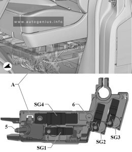
RAM 4500 (2013 – 2015) – fuse and relay box diagram

RAM 4500 (2013 – 2015) – fuse and relay box diagram

Year of production: 2013, 2014, 2015


The Ram 4500 Chassis Cab (2013 – 2015) is a heavy-duty commercial vehicle designed to handle demanding jobs requiring high towing and payload capacities. It sits between the Ram 3500 and 5500 in the Ram Chassis Cab lineup, offering excellent versatility and customization options for industries such as construction, towing, and utility services.


Power Distribution Center

Fuse box location

The Power Distribution Center is located in the engine compartment near the battery.

RAM 4500 - fuse and relay box location - engine compartment
RAM 4500 – fuse and relay box location – engine compartment


Fuse box diagram

RAM 4500 - fuse and relay box diagram - engine compartment
RAM 4500 – fuse and relay box diagram – engine compartment


Assignment of the fuses in the engine compartment (2013-2015)

Cavity Cartridge fuse Micro Fuse Description
F01 80 Rad Fan Control Module – If equipped
F03 60 Rad Fan – If Equipped
F05 40 Compressor for Air Suspension – If Equipped
F06 40 Antilock Brakes/Electronic Stability Control Pump
F07 40 Starter Solenoid
F08 30 Emissions Diesel – If Equipped
F09 40 Diesel Fuel Heater – If Equipped
F10 40 Body Controller / Exterior Lighting #2
50 Body Controller / Exterior Lighting #2 – If Equipped with Stop/Start
F11 30 Integrated Trailer Brake Module – If Equipped
F12 40 Body Controller #3 / Interior Lights
F13 40 Blower Motor
F14 40 Body Controller #4 / Power Locks
F15 30 Electric Park Brake Right Side – If Equipped
F19 30 SCR – If Equipped
F20 30 Passenger Door Module
F21 30 Drive Train Control Module
F22 20 Engine Control Module
F23 30 Body Controller #1
F24 30 Driver Door Module
F25 30 Front Wiper Low Speed
30 Front Wiper High Speed
F26 30 Antilock Brakes/Stability Control Module/Valves
F28 20 Trailer Tow Backup Lights – If Equipped
F29 20 Trailer Tow Parking Lights – If Equipped
F30 30 Trailer Tow Receptacle
F32 30 Drive Train Control Module – If Equipped
F33 20 Diesel Fuel Heater #1 – If Equipped /Rear Blower – If Equipped
F34 30 Vehicle System Interface Module #2 – If Equipped
F35 30 Sunroof – If Equipped
F36 30 Rear Defroster– If Equipped
F37 30 Diesel Fuel Heater #2 if equipped
F38 30 Power Inverter 115V AC– If Equipped
F39 30 Vehicle System Interface Module #1– If Equipped
F41 10 Active Grill Shutter
F42 20 Horn
F43 10 Snow Plow (Left) – If Equipped
F44 10 Diagnostic Port
F46 10 Tire Pressure Monitor
F47 10 Snow Plow (Right) – If Equipped
F49 10 Instrument Panel Cluster
F50 20 Air Suspension Control Module – If Equipped
F51 10 Ignition Node Module / Keyless Ignition
F52 5 Battery Sensor
F53 20 Trailer Tow – Left Turn/Stop Lights
F54 20 Adjustable Pedals
F55 20 E38 Radio – If Equipped
F56 15 Additional Diesel Content – If Equipped
F57 20 Transmission
F58 20 (Gas engine) Engine Cooling Pump
25 (Diesel engine)
F60 15 Underhood Lamp
F61 20 Power Take-off Unit – If Equipped
F62 10 Air Conditioning Clutch
F63 20 IgnitionCoils (Gas), Urea Heater (Diesel)
F64 25 Fuel Injectors / Powertrain
F65 10 USB interface
F66 10 Sunroof / Passenger Window Switches /Rain Sensor
F67 10 CD / DVD / Bluetooth Hands-free Module – If Equipped
F69 15 Mod SCR 12V – If Equipped
F70 30 Fuel Pump Motor
F71 25 Amplifier
F72 10 Voltage Stabilizer Modules – If Equipped
F74 20 (Gas engine) Brake Vacuum Pump Gas/Diesel – If Equipped
10 (Diesel engine)
F75 10 Coolant Temperature Valve Actuator
F76 10 Antilock Brakes/Electronic Stability Control
F77 10 Drivetrain Control Module/Front Axle Disconnect Module
F78 10 Engine Control Module / Electric Power Steering
F79 15 Clearance Lights
F80 10 Universal Garage Door Opener / Compass
F81 20 Trailer Tow Right Turn/Stop Lights
F82 10 Steering Column Control Module/ Cruise Control
F84 15 Switch Bank/Instrument Cluster
F85 10 Airbag Module
F86 10 Airbag Module
F87 10 Air Suspension-If Equipped / Trailer Tow / Steering Column Control Module
F88 15 Instrument Panel Cluster
F90 20 Power Outlet (Rear seats) Customer Selectable
F91
F93 20 Cigar Lighter
F94 10 Shifter / Transfer Case Module
F95 10 Rear Camera / Park Assist
F96 10 Rear Seat Heater Switch
F97 25 Rear Heated Seats & Heated Steering Wheel – If Equipped
F98 25 Front Heated Seats – If Equipped
F99 10 Climate Control
F101 15 Electrochromatic Mirror / Smart High Beams – If Equipped
F104 20 Power Outlets (Instrument Panel/Center Console)

WARNING: Terminal and harness assignments for individual connectors will vary depending on vehicle equipment level, model, and market.
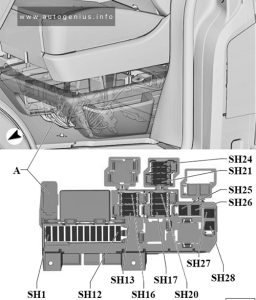
RAM 4500 (2012) – fuse and relay box diagram

RAM 4500 (2012) – fuse and relay box diagram

Year of production: 2012


The Ram 4500 (2012) is a heavy-duty chassis cab truck designed for commercial applications, sitting between the Ram 3500 and 5500 in the Ram lineup. The 2012 Ram 4500 offers a robust combination of power, durability, and upfit flexibility, making it ideal for businesses requiring a vehicle that can handle heavy loads, towing, and various custom configurations.
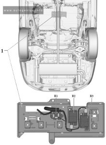
 

Totally Integrated Power Module

Fuse Box Location

The totally integrated power module (TIPM) is located in the engine compartment near the battery.

RAM 4500 - fuse and relay box location - engine compartment
RAM 4500 – fuse and relay box location – engine compartment


Fuse box diagram

RAM 4500 - fuse and relay box diagram - engine compartment
RAM 4500 – fuse and relay box diagram – engine compartment


Assignment of the fuses in the engine compartment (2012)

Cavity Cartridge fuse Mini Fuse Description
J01 40 Trailer Tow
J02 30 Electric Brake
J03 30 Diesel Powertrain Control Module – If Equipped
J04 25 Driver Door Node
J05 25 Passenger Door Node
J06 40 Antilock Brakes Pump/Stability Control System
J07 30 Antilock Brakes Valve/Stability Control System
J08 40 Power Seat
J10 30 Sway Bar Module – If Equipped
J11 30 Transfer Case Module
J12 30 Rear Defroster
J13 60 Main Ignition Off Draw (IOD) Fuse
J14 20 Trailer Tow Lamps/Park Lamps
J15 40 Front Blower
J17 40 Starter Motor Solenoid
J18 20 Powertrain Control Module Transmission Range
J19 60 Rad Fan Motor HI/Rad Fan Motor Low
J20 30 Front Wiper Ground/Low/High
J21 20 Washer Control
J22 25 Sunroof Module
M1 15 Stop Switch Lamp
M5 25 115V AC Inverter
M6 20 Power Outlet (Instrument Panel or Front Console)/Rain Snsr
M7 20 Power Outlet (Rear Console or Center Seat)
M8 20 Front Heated Seat & Steering Wheel
M9 20 Rear Heated Seats
M10 15 Hands Free Module/Vanity Lamp/Universal GarageDoor Opener Module
M11 10 Climate Control System
M12 30 Radio/Amplifier
M13 20 Main #2 Instrument Cluster/Wireless Control Module/ITM/
Siren/Multifunction Switch (Steering Column Module)
M14 20 Back Up Camera (Domestic Only)
M15 20 Power Seat Module(s)/Audio Telematics/Daytime Running Lights Relay/Instrument Cluster/Transfer Case Module
M16 10 Airbag Module
M18 15 Center Stop Lamp
M19 25 Automatic Shutdown 1 and 2
M20 15 Instrument Cluster Interior Lighting /Sw Steering Wheel/Sw Bank
M21 20 Automatic Shutdown 3
M22 10 Horns (Low/High) – Right
M23 10 Horns (Low/High) – Left
M25 20 Fuel Pump Motor/Diesel Lift Pump – If Equipped
M26 10 Driver’s Door Switch
M27 10 Ignition Switch
M28 15 Powertrain Control Module
M29 10 Tire Pressure Monitor
M30 15 J1962 Diag Connector
M31 20 Back-Up Lamps
M32 10 Airbag Module
M33 10 Powertrain Control Module
M34 10 Park Assist Module/Climate Control System Module/IR Sensor/Compass Module
M35 15 Left Front & Rear Parklamps
M36 20 Power Outlet (Instrument Panel or Center Console)
M37 10 Antilock Brakes/Stability Control System Module/Stoplamp Switch
M38 25 All Door Lock &Unlock

WARNING: Terminal and harness assignments for individual connectors will vary depending on vehicle equipment level, model, and market.