Mazda CX-50 (2023 – 2025) – fuse and relay box diagram
Year of production: 2023, 2024, 2025
The Mazda CX-50 compact crossover has been available from 2023 to the present. In this guide, you will find fuse box diagrams for the 2023 and 2024 Mazda CX-50 models, details on the locations of the fuse panels within the vehicle, and information about the function and layout of each fuse.
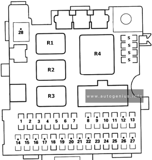
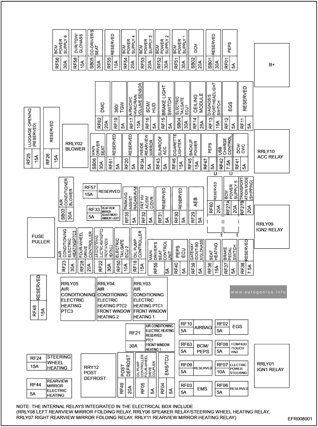
Passenger Compartment Fuse Panel
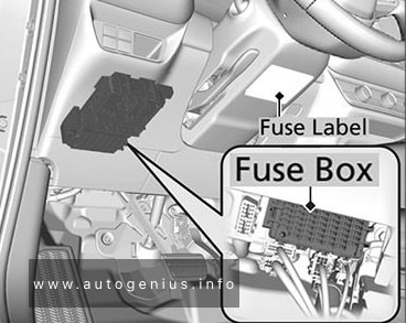
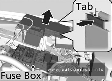
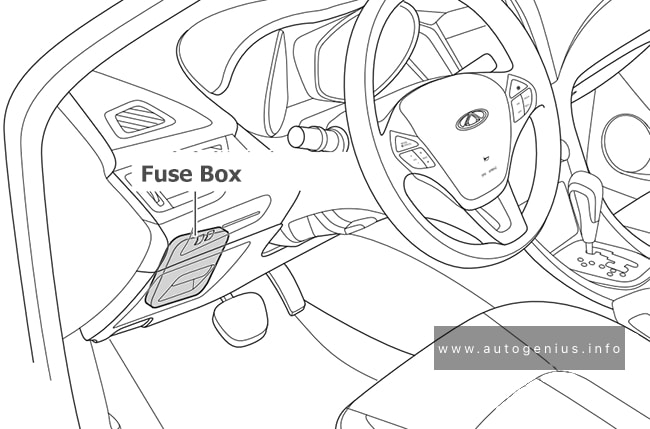
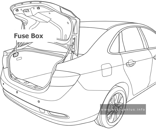
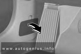
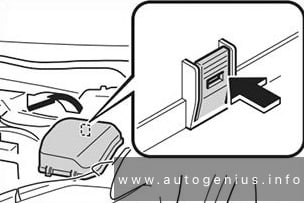
Fuse Box Location
The fuses are located behind the cover on the vehicle’s left side.
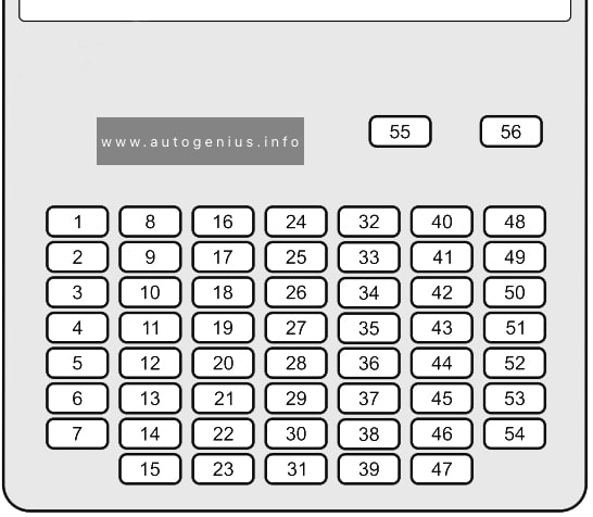
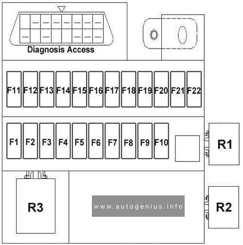
Fuse Box Diagram
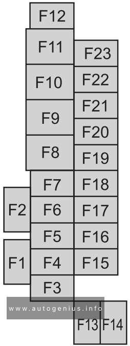
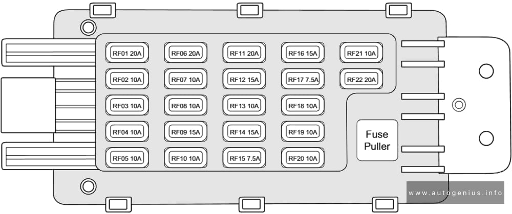
Assignment of the fuses in the instrument panel
| № | Amps | PROTECTED COMPONENT |
|---|---|---|
| F1 | – | – |
| F2 | – | – |
| F3 | 20A | Front seat warmer |
| F4 | 15A | Power door locks (Driver) |
| F5 | 15A | Power door locks (Passenger) |
| F6 | 20A | Rear seat warmer |
| F7 | 25A | Power liftgate |
| F8 | 30A | Power seat (Passenger) |
| F9 | 30A | Power windows (Driver) |
| F10 | 30A | Power windows (Passenger) |
| F11 | 30A | Power seat (Driver) |
| F12 | – | – |
| F13 | 15A | Audio |
| F14 | 25A | Audio |
| F15 | 15A | Liftgate lock |
| F16 | 15A | Illumination |
| F17 | 10A | Brake lights |
| F18 | 10A | Reverse lights |
| F19 | 10A | Rear turn signal lights |
| F20 | 10A | Taillights |
| F21 | 10A | Taillights |
| F22 | 7.5A | Air bag |
| F23 | – | – |
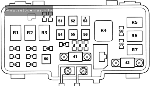
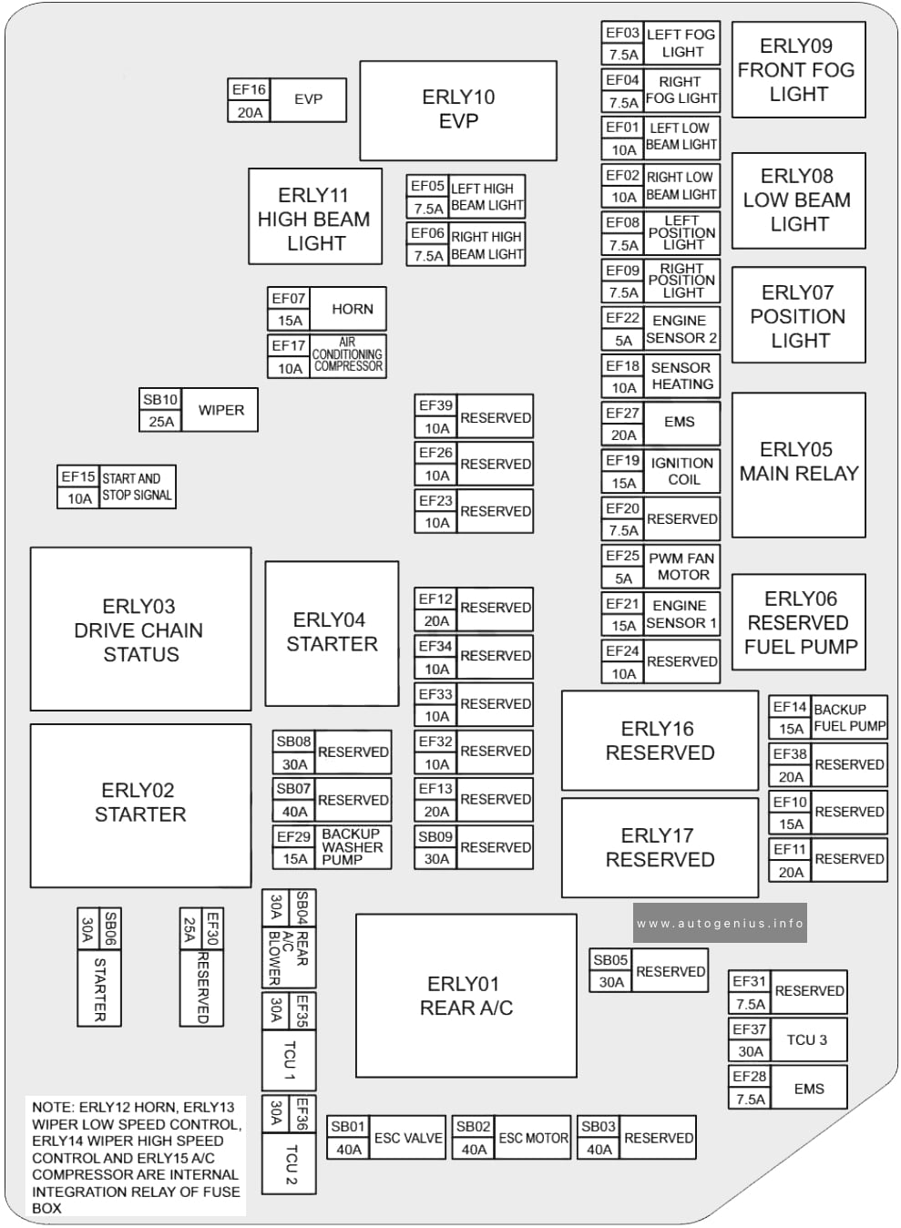
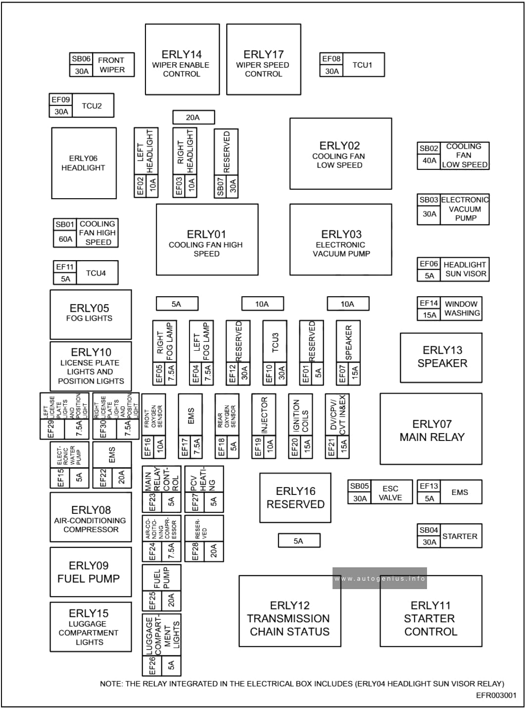
Engine Compartment Fuse Box
Fuse Box Location
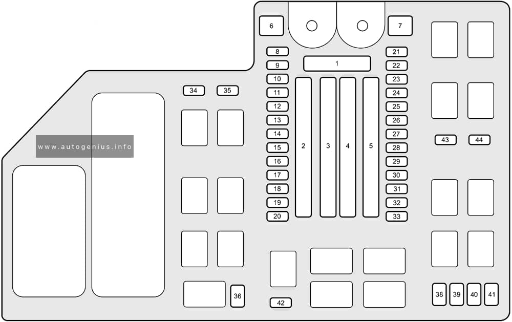
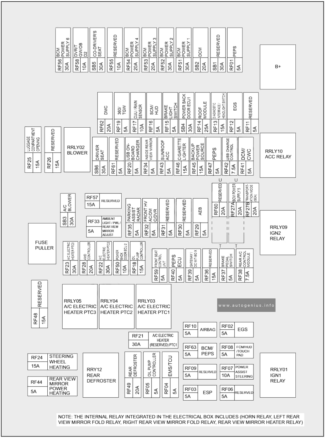
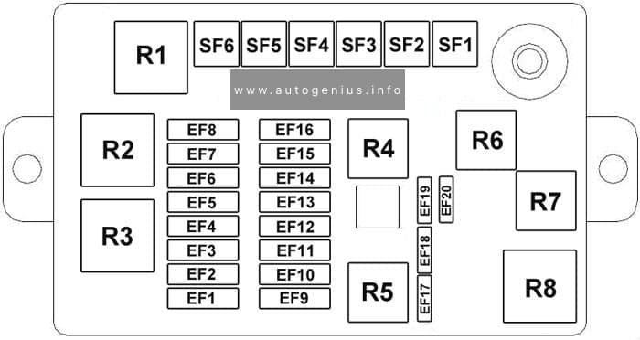
Fuse Box Diagram
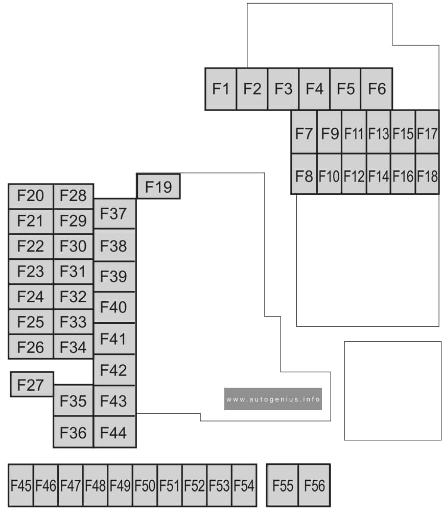
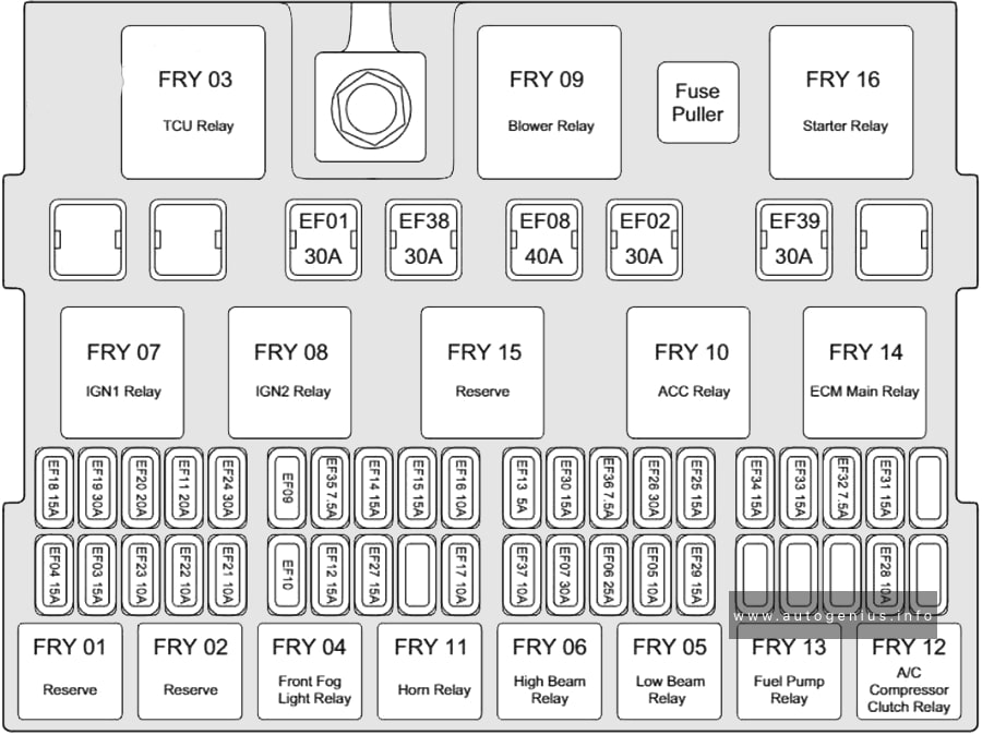
Assignment of the fuses in the engine compartment
| № | Amps | PROTECTED COMPONENT |
|---|---|---|
| F1 | – | – |
| F2 | 20A | Windshield wiper de-icer |
| F3 | 30A | Engine control system |
| F4 | 20A | S-VT |
| F5 | 40A | Engine control system |
| F6 | – | – |
| F7 | 20A | Fuel pump |
| F8 | 15A | Engine control system |
| F9 | 15A | Transmission control system |
| F10 | 10A | Engine control system |
| F11 | 7.5A | Air conditioner |
| F12 | 15A | Engine control system |
| F13 | – | – |
| F14 | 15A | Electric water pump |
| F15 | – | – |
| F16 | 15A | For protection of various circuits |
| F17 | – | – |
| F18 | 15A | For protection of various circuits |
| F19 | 60A | Power steering system |
| F20 | 15A | Headlight (LH) 1 |
| F21 | 15A | Headlight (RH) 1 |
| F22 | 15A | Keyless system |
| F23 | 30A | ABS, Dynamic stability control system |
| F24 | 15A | Headlight (LH) 2 |
| F25 | 15A | Headlight (RH) 2 |
| F26 | 7.5A | On board diagnostics |
| F27 | 25A | For protection of various circuits |
| F28 | 25A | For protection of various circuits |
| F29 | 15A | Windshield washer |
| F30 | 15A | Accessory sockets |
| F31 | 15A | Horn |
| F32 | – | – |
| F33 | – | – |
| F34 | – | – |
| F35 | 50A | ABS, Dynamic stability control system |
| F36 | – | – |
| F37 | 30A | Rear window defogger |
| F38 | 50A | For protection of various circuits |
| F39 | – | – |
| F40 | 40A | Air conditioner |
| F41 | 30A | Audio |
| F42 | 20A | Windshield wipers |
| F43 | 30A | Cooling fan |
| F44 | 30A | Starter |
| F45 | 10A | Engine control system |
| F46 | 15A | Audio |
| F47 | 15A | For protection of various circuits |
| F48 | 7.5A | Air bag |
| F49 | 15A | Instrument cluster |
| F50 | 15A | Room light |
| F51 | 15A | Panorama sunroof |
| F52 | 15A | Panorama sunroof |
| F53 | 15A | Engine control system |
| F54 | 15A | i-ACTIVSENSE |
| F55 | 50A | For protection of various circuits |
| F56 | – | – |
WARNING: Terminal and harness assignments for individual connectors will vary depending on vehicle equipment level, model, and market.