Chery Tiggo 8 PRO (2020 – 2023) – fuse and relay box diagram
Year of production: 2020, 2021, 2022, 2023
The Chery Tiggo 8 PRO, a mid-size crossover, has been available since 2020 and continues to be produced. In this guide, you’ll find fuse box diagrams for the 2020, 2021, 2022, and 2023 models. It also provides information on the location of the fuse panels inside the vehicle, along with details about the fuse assignments (fuse layout) and relays.
Passenger Compartment Fuse Panel
Fuse Box Location
The fuses are located on the lower left side of instrument panel.
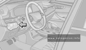
Fuse Box Diagrams
Version 1 (T1D 1.6T+7DCT)
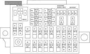
Assignment of the fuses in the instrument panel (T1D)
| № | Description |
|---|---|
| RF01 | BCM & Instrument Panel & PEPS & Gateway |
| RF02 | – |
| RF03 | EPS & Angle Sensor |
| RF04 | Audio |
| RF05 | Airbag Module |
| RF06 | A/C Control Panel & Rear Speed Resistor Panel & Automatic A/C Control Module & Bluetooth Module & T-BOX Module & Instrument Panel Ambient Light & Wireless Charging Module |
| RF07 | A/C Control Panel & Rear Speed Resistor Panel & TCU (7DCT) & T-BOX Module & FIDC Switch & Automatic A/C Control Module & Negative Ion Generator |
| RF08 | Door Ambient Light & Panoramic Controller & Kick sensor & Camera & Driving Recorder |
| RF09 | – |
| RF10 | – |
| RF11 | – |
| RF12 | – |
| RF13 | TCU (CVT25) |
| RF14 | – |
| RF15 | Auxiliary Fasia Console Switch (DCT) & OBD Diagnostic Interface & Spiral Cable & Center Console Switch |
| RF16 | – |
| RF17 | – |
| RF18 | Power Rear View Mirror Motor |
| RF19 | – |
| RF20 | Rrly01 Blower RLY |
| RF21 | PEPS & Gateway & EPB & Shift Switch |
| RF22 | – |
| RF23 | RRLY02 Steering Sheel Heat RLY |
| RF24 | RRLY03 Defoger RLY |
| RF25 | – |
| RF26 | BCM & Audio & Power Rear View Mirror Switch & Mobile Wireless Charging Module |
| RF27 | Spare Power |
| RF28 | USB Charging Module & Driving Recorder Charging Port |
Version 2 (T1A 2.0T+CVT25)
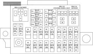
Assignment of the fuses in the instrument panel (T1A)
| № | Description |
|---|---|
| RF01 | Instrument Cluster & BCM & Center Gateway & GLONASS & PEPS |
| RF02 | – |
| RF03 | EPS & Angle Sensor |
| RF04 | – |
| RF05 | Airbag Module |
| RF06 | – |
| RF07 | Auto A/C Control Module & Audio & Adjustment Switch Assembly & Auxiliary Fascia Console Switch Assembly & Gear backlight (CVT25) & Gearshift mechanism (CVT25) |
| RF08 | – |
| RF09 | Radio Contrl Module |
| RF10 | Instrument Cluster & A/C Control Panel (AUTO) & Right Mixing Damper Motor & Left Mixing Damper Motor & Mode Damper Motor & Inner and outer Circulation Motor & GLONASS & T-BOX MODULE |
| RF11 | – |
| RF12 | – |
| RF13 | TCU (CVT25) |
| RF14 | – |
| RF15 | Instrument Panel Ambient Lamp & Auxiliary Instrument Panel Ambient Lamp & Spiral Cable & Center Console Switch & EPB Switch & OBD Diagnose Port & T-box Module |
| RF16 | – |
| RF17 | – |
| RF18 | A/C Control Panel & Power Rear View Mirror Motor |
| RF19 | – |
| RF20 | Rrly 01 Blower RLY |
| RF21 | PEPS & Center Gateway |
| RF22 | – |
| RF23 | RRLY02 steering wheel heat RLY |
| RF24 | RRLY03 DEFROST RLY |
| RF25 | – |
| RF26 | BCM & Radio & Power Rear View Mirror Switch |
| RF27 | Spare Power Supply |
| RF28 | USB Charging Module |
Engine Compartment Fuse Panel
Fuse Box Location
The fuse box is located on the left side of engine compartment and the rear side of left headlight.
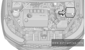
Fuse Box Diagrams
Version 1 (T1D 1.6T+7DCT)
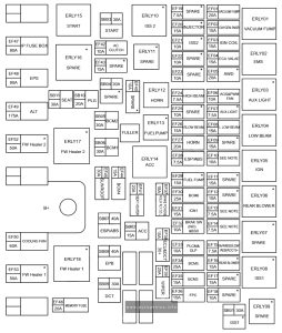
Assignment of the fuses in the instrument panel (T1D)
| № | Description |
|---|---|
| SB01 | ISS1 |
| SB02 | ACC |
| SB03 | Start control |
| SB04 | – |
| SB05 | BCM 2 |
| SB06 | BCM 1 |
| SB07 | ESP & ABS |
| SB08 | ESP(EPB) |
| SB09 | DCT |
| SB10 | PLG |
| SB11 | Seat adjustment |
| EF01 | ERLY 01 vacuum pump RLY |
| EF02 | Oxygen sensor |
| EF03 | Ignition coil |
| EF04 | ECU solenoid valve |
| EF05 | AWD |
| EF06 | AGS & PWM FAN |
| EF07 | AUX Light |
| EF08 | Left Low beam power |
| EF09 | – |
| EF10 | ECU & Start RLY Coil (For ISS) |
| EF11 | – |
| EF12 | – |
| EF13 | ECU & TCU & Brake SW (NC) & FPC 15+ |
| EF14 | Compressor Pipe Press Switch & Reverse Radar Module & Sunroof & DVR & Seat Ventilation & AFS & MST & RACP |
| EF15 | AVW & BSD & LDW & AEB & ACC15+ |
| EF16 | Rear Blower |
| EF17 | – |
| EF18 | – |
| EF19 | – |
| EF20 | Injector Cyl 1,2,3,4 |
| EF21 | ISS2 |
| EF22 | – |
| EF23 | – |
| EF24 | High beam |
| EF25 | – |
| EF26 | Right Low beam power |
| EF27 | ERLY12 Horn RLY |
| EF28 | ESP & ABS |
| EF29 | ERLY13 Fuel Pump RLY |
| EF30 | BCM 6 |
| EF31 | IGN1 |
| EF32 | Brake SW & BSD |
| EF33 | PLGM & GLP |
| EF34 | BCM 5 |
| EF35 | BCM 3 |
| EF36 | FPC |
| EF37 | Spare Power & R BLW RLY COIL |
| EF38 | ECU & DCT 30+ |
| EF39 | Wiper RLY |
| EF40 | – |
| EF41 | Seat Heater |
| EF42 | A/C clutch |
| EF43 | – |
| EF44 | BCM 4 |
| EF45 | Sunroof |
| EF46 | Memory Fuse |
| EF47 | IP Fuse Box power |
| EF48 | EPS power |
| EF49 | ALT power |
| EF50 | Cooling Fan |
| EF52 | FW Heater 2 |
| EF53 | FW Heater 1 |
Version 2 (T1A 2.0T+CVT25)
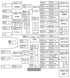
Assignment of the fuses in the engine compartment (T1A)
| № | Description |
|---|---|
| SB01 | ISS 1 |
| SB02 | ACC |
| SB03 | Start control |
| SB04 | – |
| SB05 | BCM 2 |
| SB06 | BCM 1 |
| SB07 | ESP (EPB) |
| SB08 | ESP (EPB) |
| SB09 | DCT |
| SB10 | PLG |
| SB11 | Seat adjustment SEAT |
| EF01 | ERLY 01 vacuum pump RLY |
| EF02 | OXYGEN SENSOR |
| EF03 | Ignition coil |
| EF04 | ECU solenoid valve |
| EF05 | – |
| EF06 | Cooling Fan |
| EF07 | – |
| EF08 | Left Low beam power |
| EF09 | – |
| EF10 | ECU & Start RLY Coil (For ISS) |
| EF11 | – |
| EF12 | – |
| EF13 | ECU & TCU & brake SW |
| EF14 | Reverse Radar Module & Sunroof & Seat Control Module & Anti Glare Interior Rear view Mirror & Rear A/C Panel |
| EF15 | 360 Camera Module |
| EF16 | Rear Blower |
| EF17 | – |
| EF18 | – |
| EF19 | – |
| EF20 | Injector Cyl 1,2,3,4 |
| EF21 | ISS 2 |
| EF22 | – |
| EF23 | – |
| EF24 | ERLY20 High beam RLY |
| EF25 | – |
| EF26 | Right Low beam power |
| EF27 | ERLY12 horn RLY |
| EF28 | ESP (EPB) |
| EF29 | ERLY 13 fuel pump RLY |
| EF30 | BCM 6 |
| EF31 | IGN (a) & IGN (b) |
| EF32 | Brake Switch & 360 Camera Module |
| EF33 | PLG & Kick Sensor & Door Ambient Lamp |
| EF34 | BCM 5 |
| EF35 | BCM 3 |
| EF36 | – |
| EF37 | The Third Spare Power Supply & Trunk Spare power supply |
| EF38 | ECU |
| EF39 | Wiper RLY |
| EF40 | – |
| EF41 | Seat Heater |
| EF42 | ERLY 19 AC clutch RLY |
| EF43 | – |
| EF44 | BCM 4 |
| EF45 | Sunroof |
| EF46 | IP Fuse Box power |
| EF47 | IP Fuse Box power |
| EF48 | EPS power |
| EF49 | ALT power |
| EF50 | COOLING FAN |
| EF52 | FW Heater 2 RLY |
| EF53 | FW Heater 1 RLY |
WARNING: Terminal and harness assignments for individual connectors will vary depending on vehicle equipment level, model, and market.
