Skoda Kamiq (2019 – 2020) – fuse and relay box diagram
Year of production: 2019, 2020
The Škoda Kamiq is a compact crossover SUV produced by the Czech automaker Škoda Auto. It was introduced in 2019 as the smallest SUV in Škoda’s lineup, sitting below the larger Škoda Karoq and Škoda Kodiaq. The Kamiq offers a combination of practicality, modern technology, and affordability, making it a popular choice in the growing compact SUV market.
Key Features of the Škoda Kamiq:
1.Compact Size: As a compact crossover, the Kamiq is designed for urban environments where its smaller footprint allows for easier parking and maneuvering, yet it still provides SUV-like advantages such as a higher driving position.
2.Interior Space: Despite its compact size, the Kamiq offers a spacious interior with good legroom for both front and rear passengers, as well as a reasonably sized boot (400 liters, expandable to 1,395 liters with rear seats folded).
3.Modern Design: The Kamiq sports Škoda’s signature design language, with a bold front grille, split headlights with LED daytime running lights, and a clean, angular body style that gives it a contemporary, sharp look.
4.Engine Options:
•The Kamiq is available with a range of petrol and diesel engines in various markets, including efficient 1.0-liter and 1.5-liter TSI petrol engines, and a 1.6-liter TDI diesel engine.
•Some variants offer mild-hybrid technology for improved fuel economy.
5.Technology and Infotainment: It comes equipped with Škoda’s latest infotainment systems, including an 8-inch or optional 9.2-inch touchscreen with Apple CarPlay, Android Auto, and MirrorLink compatibility. It also offers a digital instrument cluster (Virtual Cockpit) on higher trims.
6.Safety Features: The Kamiq includes advanced safety technologies such as:
•Lane Assist and Front Assist (autonomous emergency braking).
•Adaptive Cruise Control.
•Blind Spot Detection and Rear Traffic Alert.
•Multiple airbags, including curtain airbags and side airbags.
•Euro NCAP gave the Kamiq a 5-star safety rating.
7.Driving Modes: The Kamiq offers various driving modes (Eco, Normal, Sport, Individual) depending on the trim, allowing drivers to tailor the car’s performance to their preferences.
Performance and Driving:
The Kamiq delivers a comfortable and composed driving experience, suited for city driving as well as light off-road use. The suspension is tuned for comfort, and it handles well, with light and responsive steering. Its higher driving position provides good visibility, while the engine options balance performance and fuel efficiency, especially the 1.5-liter TSI engine, which offers a balance of power and economy.
Practicality and “Simply Clever” Features:
As with other Škoda models, the Kamiq includes many of the brand’s signature “Simply Clever” features, like:
•An umbrella in the driver’s door.
•Ice scraper inside the fuel filler cap.
•Removable boot light that doubles as a flashlight.
•Adjustable cargo floor.
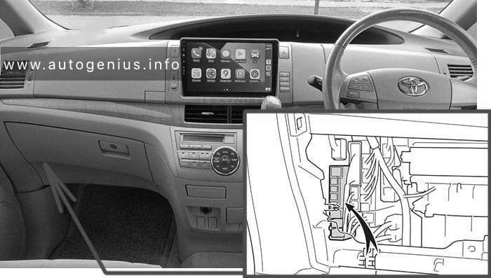
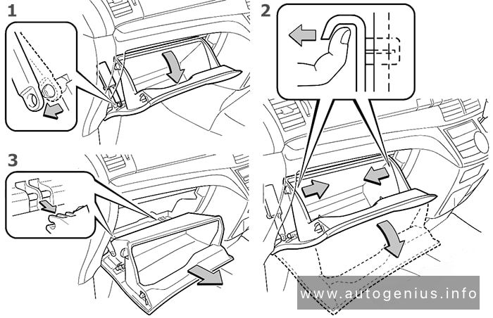
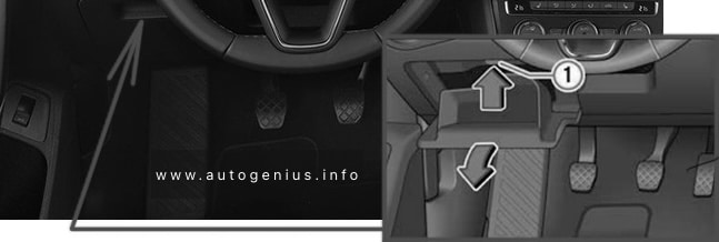
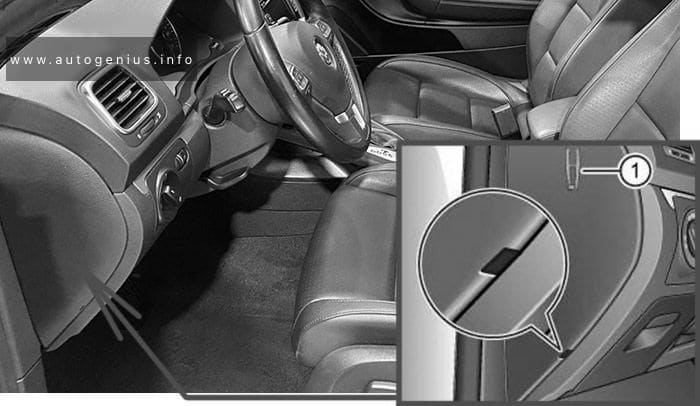
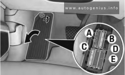
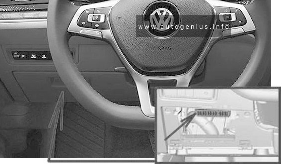
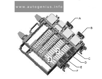
Fuse box in passenger compartment
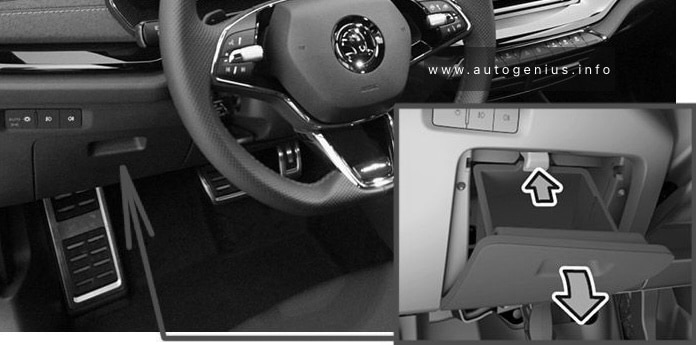
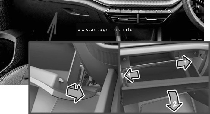
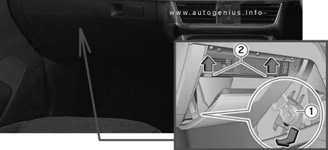
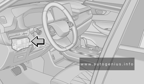
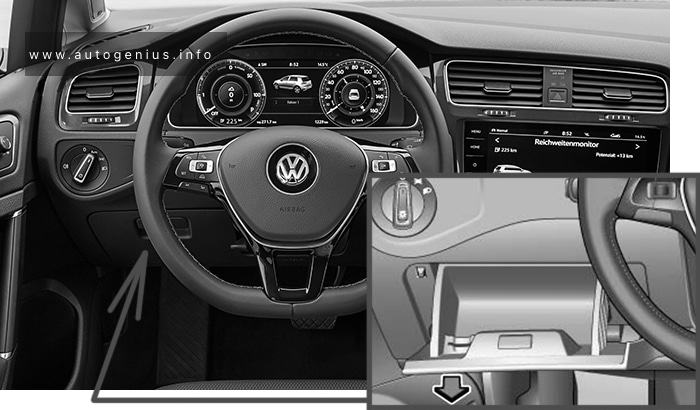
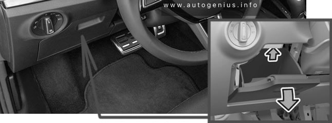
Fuse Box Location
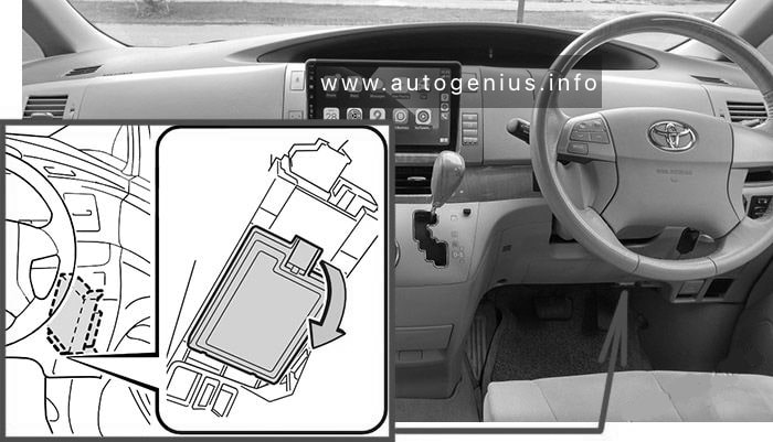
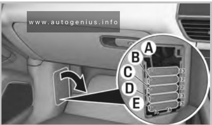
The fuse box is located behind the storage compartment on the driver’s side of the dashboard.
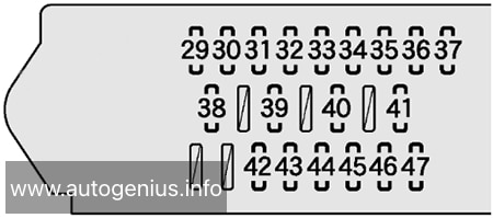
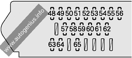
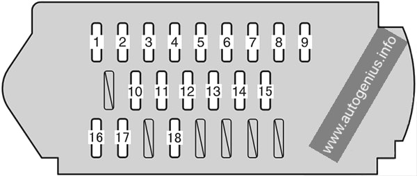
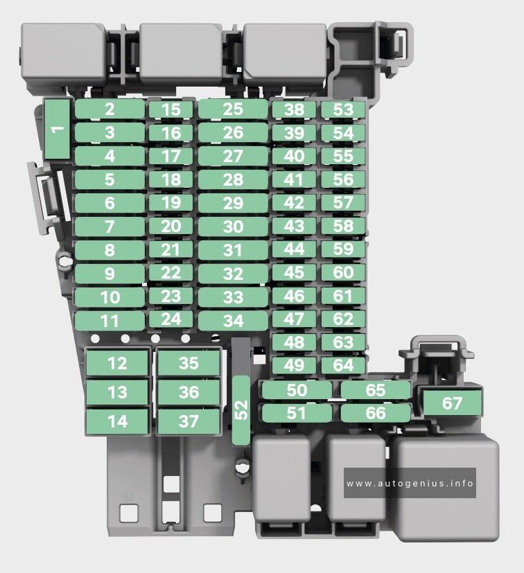
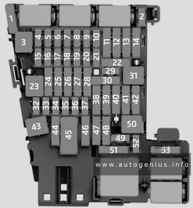
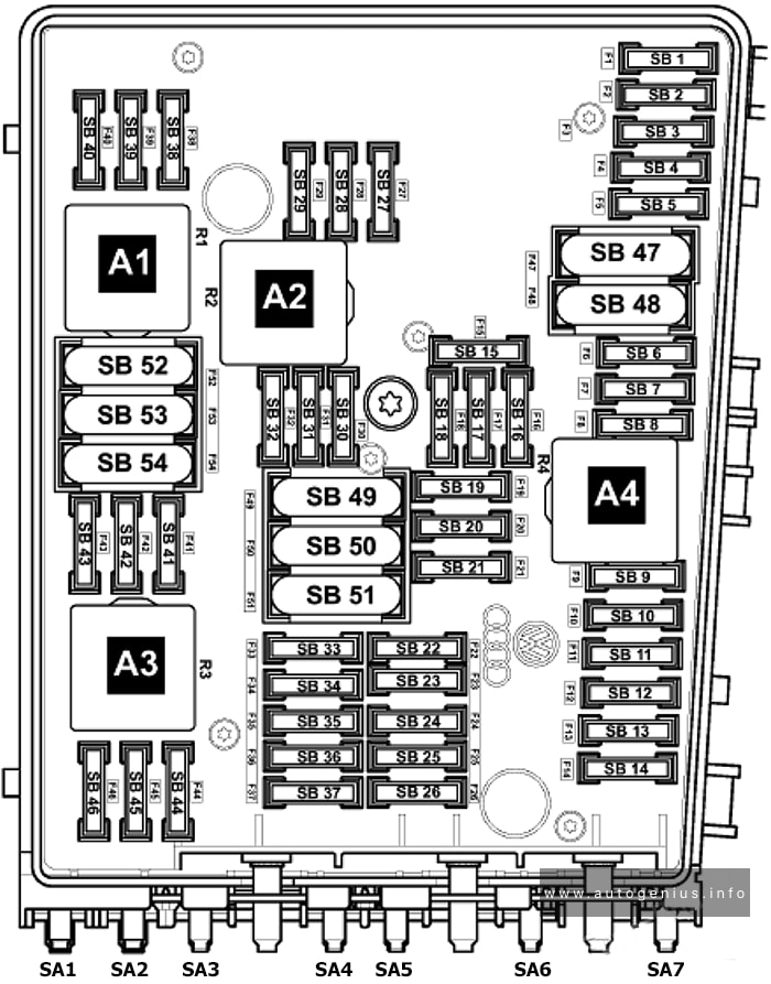
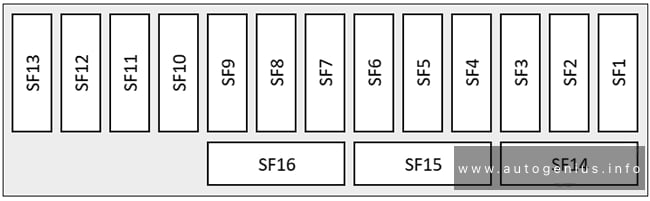
Fuse Box Diagram
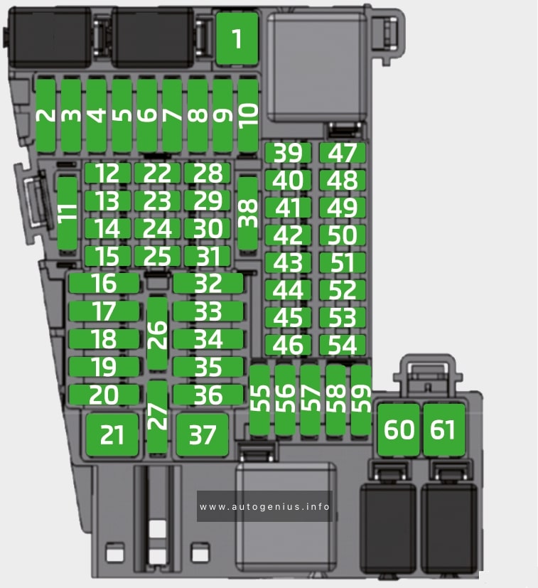
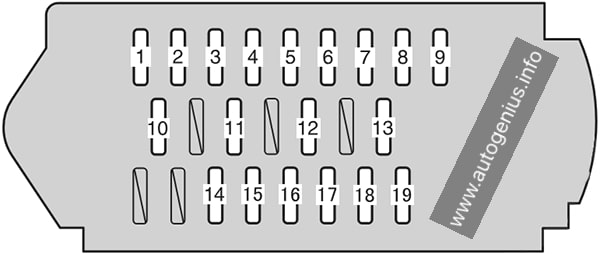
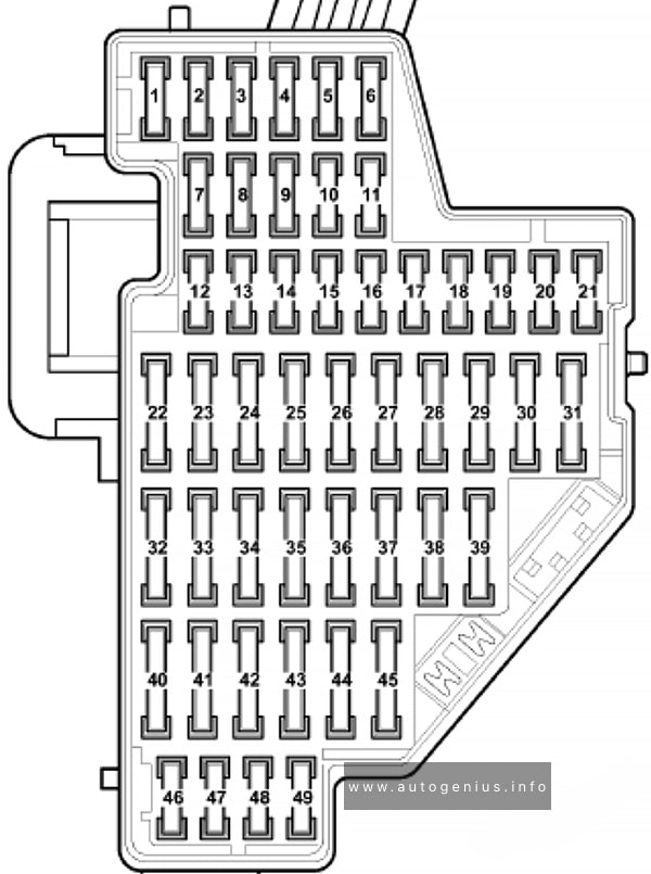
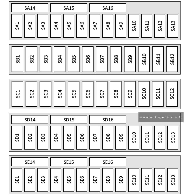
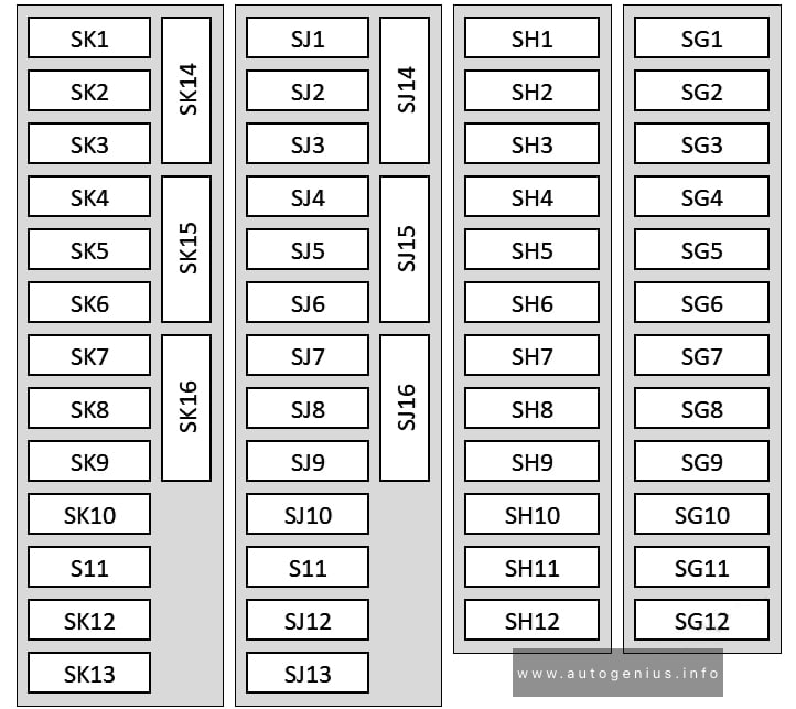
Assignment of the fuses in the Instrument panel (2019, 2020)
| № | Description |
|---|---|
| 1 | Tow hitch |
| 2 | LED headlights – left side |
| 3 | Music amplifier |
| 4 | Headlight washers |
| 5 | Tilting/sliding sunroof |
| 6 | Central locking, windscreen washer, rear window wiper |
| 7 | Seat heating – rear |
| 8 | Climatronic |
| 9 | LED headlights – right side |
| 10 | Tow hitch |
| 11 | Electric boot lid |
| 12 | Heated steering wheel |
| 13 | Light switch, diagnosis connection, rain sensor, control lever under the steering wheel, front windscreen heating |
| 14 | Windscreen washer system |
| 15 | Instrument cluster, emergency call |
| 16 | Light – right side |
| 17 | Electric windows – right side |
| 18 | Windscreen wiper |
| 19 | Infotainment |
| 20 | Heated rear window |
| 21 | SCR (AdBlue) |
| 22 | Not used |
| 23 | Reversing camera |
| 24 | Phonebox, GSM antenna, USB connection, Infotainment screen |
| 25 | Control lever under the steering wheel |
| 26 | Databus |
| 27 | Shock absorber adjustment (adaptive suspension) |
| 28 | Alarm system sensor |
| 29 | Alarm system horn |
| 30 | Ignition (ignition lock) |
| 31 | Air conditioning, heating |
| 32 | Passenger belt tensioners |
| 33 | Electric windows – left side |
| 34 | Driver belt tensioners |
| 35 | Light – left side |
| 36 | Horn |
| 37 | Heating of the front seats |
| 38 | Interior lighting, button lighting, headlight cleaning system, ambient lighting, manual air conditioning, heating |
| 39 | Assist systems |
| 40 | Light switch, headlights, headlight levelling, diagnostic connection, reversing light switch, control lever under the steering wheel |
| 41 | Interior mirror dimming, exterior mirror adjustment |
| 42 | Clutch pedal switch, engine start, air conditioning |
| 43 | Rear window wiper |
| 44 | Airbag system, airbag control lamp |
| 45 | Windscreen wiper |
| 46 | Seat heating – rear |
| 47 | Not used |
| 48 | Electric steering column lock, Kessy (keyless lock and start system) |
| 49 | SCR (AdBlue) |
| 50 | USB connections at the back |
| 51 | Not used |
| 52 | Front cigarette lighter /12 volt socket |
| 53 | Ignition key trigger lock, automatic transmission |
| 54 | 12 volt socket in the luggage compartment |
| 55 | Not used |
| 56 | Manual air conditioning, heating |
| 57 | Not used |
| 58 | Windscreen washer system |
| 59 | Exterior mirror heating, washer nozzle heating |
| 60 | Tow hitch |
| 61 | Tow hitch |
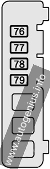
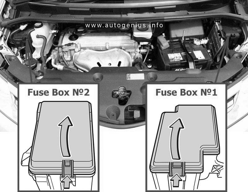
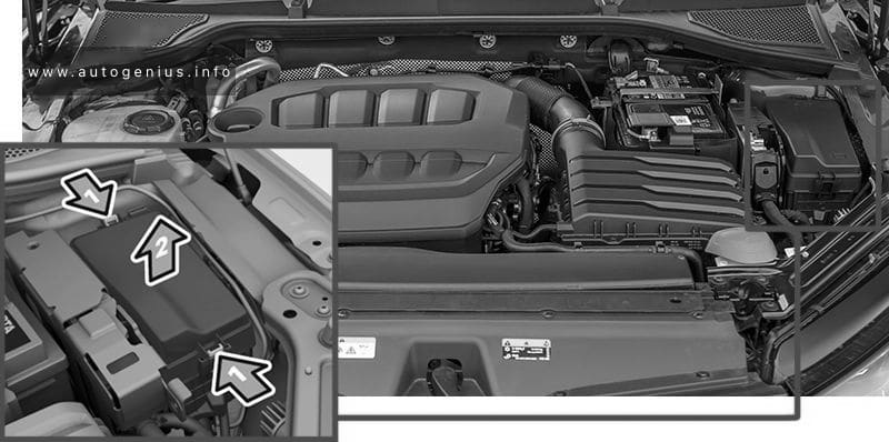
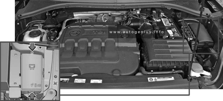
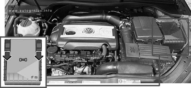
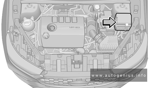
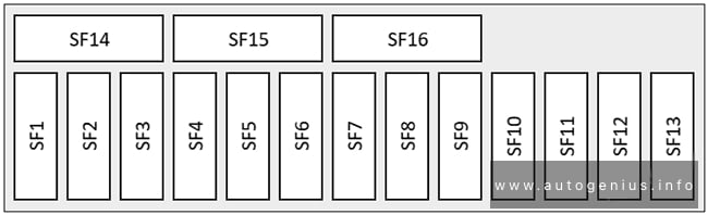
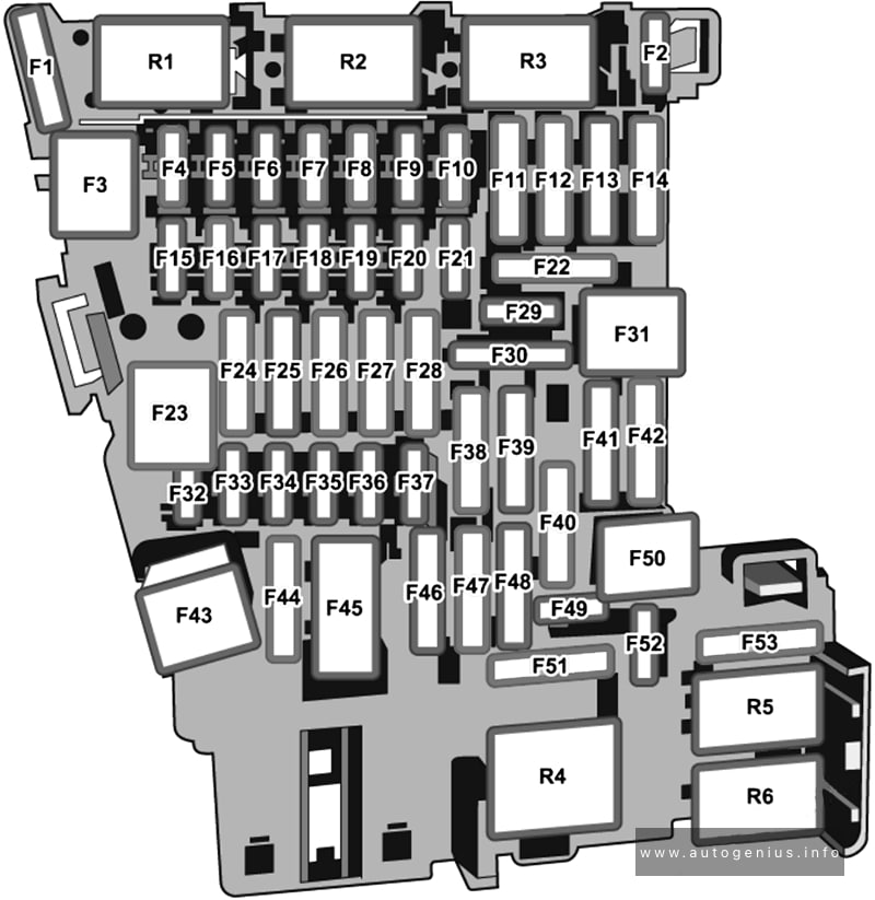
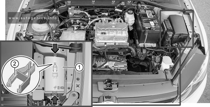
Fuse box in engine compartment
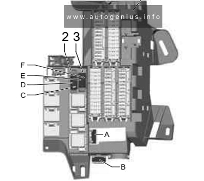
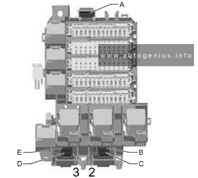
Fuse Box Location
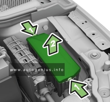
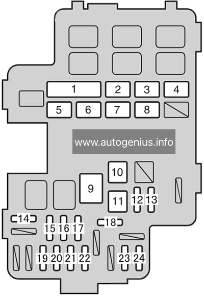
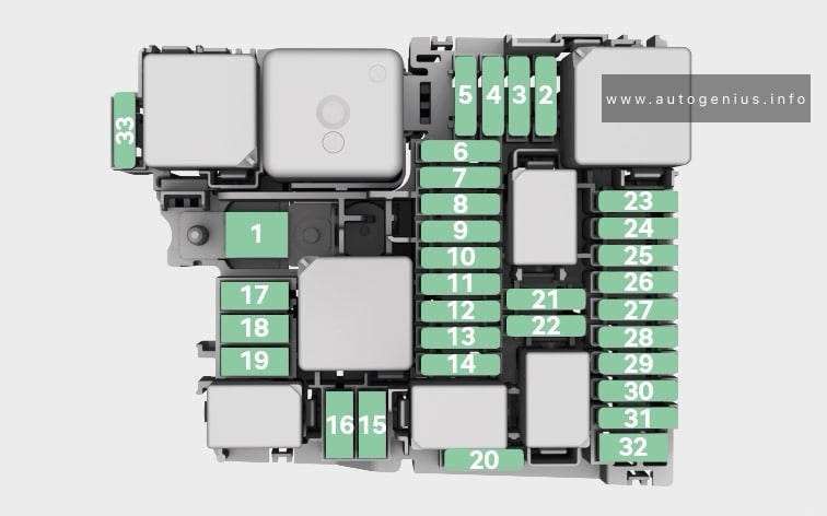
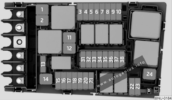
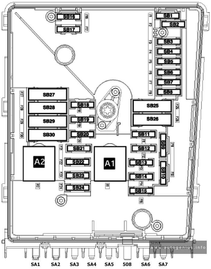
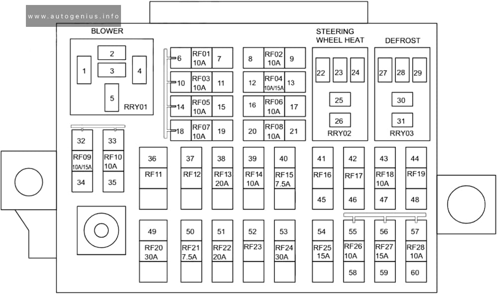
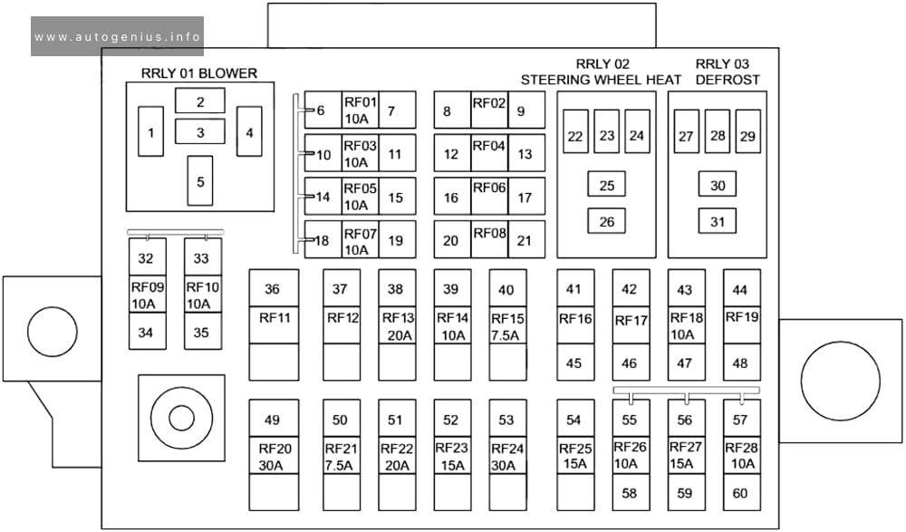
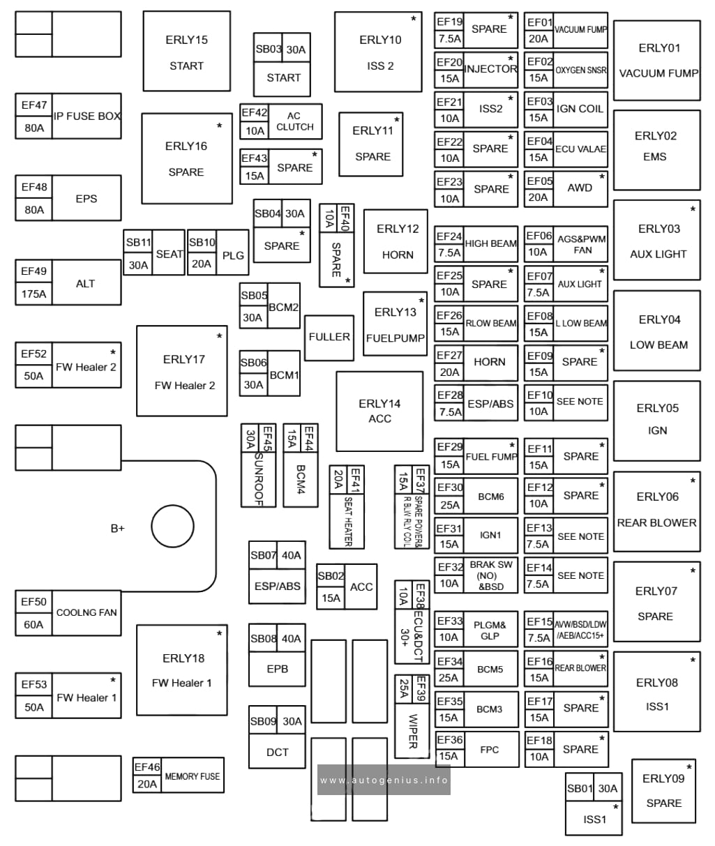
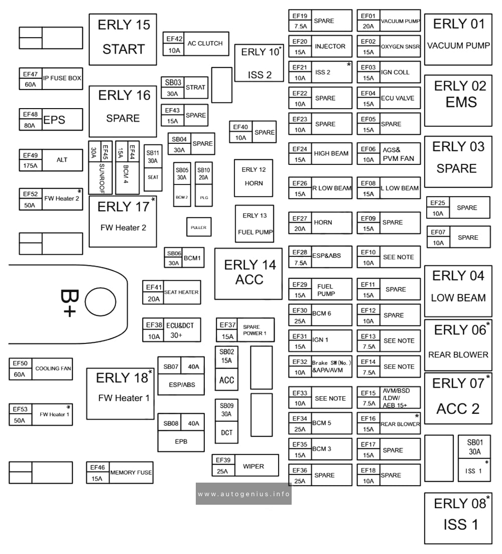
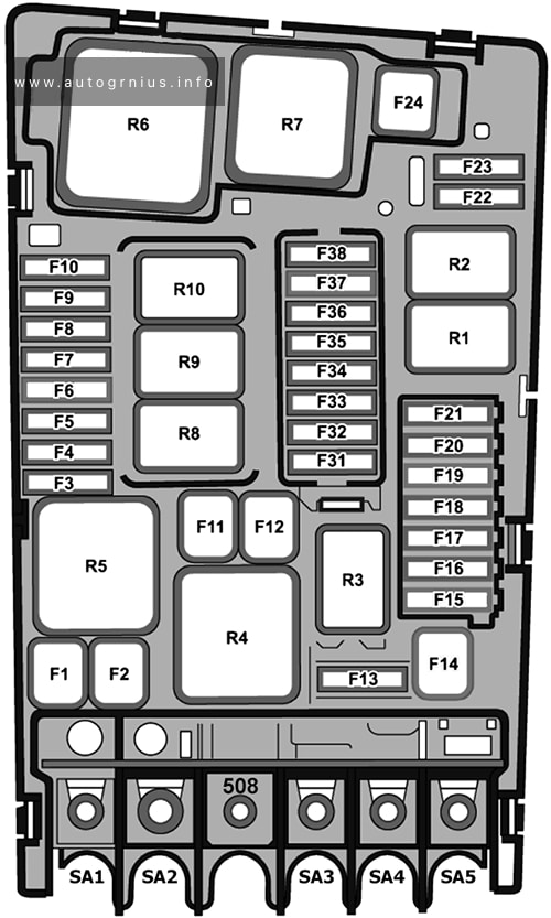
Fuse Box Diagram
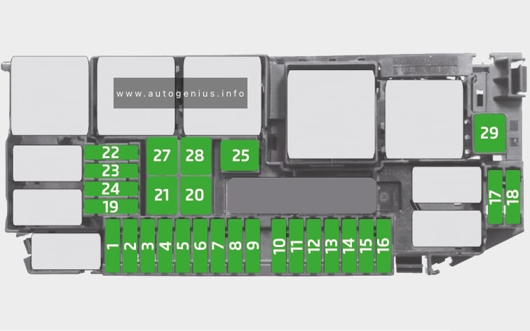
Assignment of the fuses in the engine compartment (2019, 2020)
| № | Description |
|---|---|
| 1 | Engine control unit |
| 2 | Exhaust flap, coolant pump, radiator blinds, SCR (AdBlue), engine components |
| 3 | Lambda sensors, NOx control unit |
| 4 | Fuel pump, engine components |
| 5 | Radiator fan, boost pressure regulator, oil level and oil temperature sensor, engine components |
| 6 | Crankcase breather, glow plug system, engine components |
| 7 | Brake system (vacuum pump) |
| 8 | Fuel pump, engine components |
| 9 | Brake light switch |
| 10 | Databus, BCM controller, battery data module |
| 11 | Not used |
| 12 | Air Conditioning |
| 13 | Not used |
| 14 | ESC, engine control system, engine components |
| 15 | Automatic gearbox |
| 16 | Not used |
| 17 | Engine control system |
| 18 | Starter |
| 19 | Not used |
| 20 | ESC |
| 21 | ESC |
| 22 | Not used |
| 23 | Not used |
| 24 | Not used |
| 25 | Electric auxiliary heater, radiator fan |
| 27 | Electric auxiliary heater, radiator fan |
| 28 | Electric auxiliary heater |
| 29 | Heated windscreen |
WARNING: Terminal and harness assignments for individual connectors will vary depending on vehicle equipment level, model, and market.