Volkswagen Atlas (2023 – 2024) – fuse and relay box diagram
Year of production: 2023, 2024
This article provides fuse box diagrams for the 2023 and 2024 Volkswagen Atlas, along with details on the location of the fuse panels within the vehicle. You’ll also find information on the fuse and relay assignments (fuse layout).
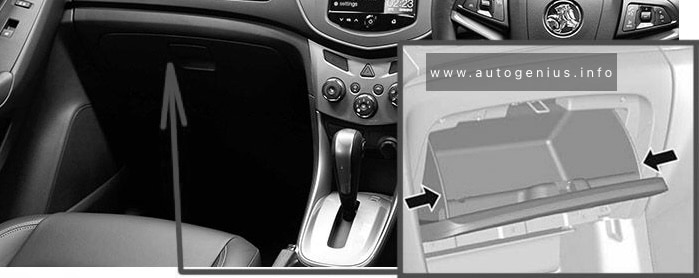
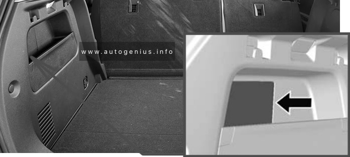
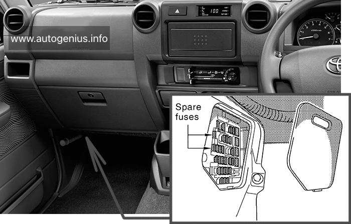
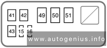
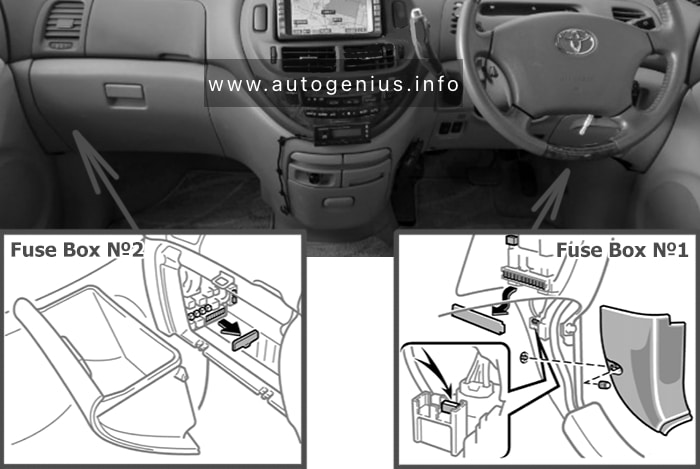
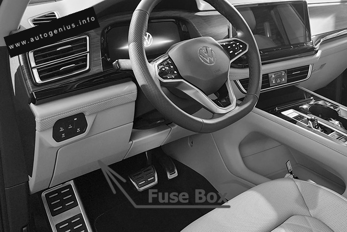
Passenger Compartment Fuse Box
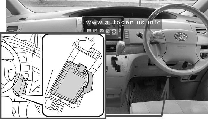
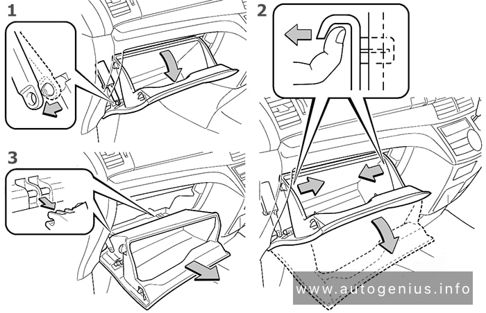
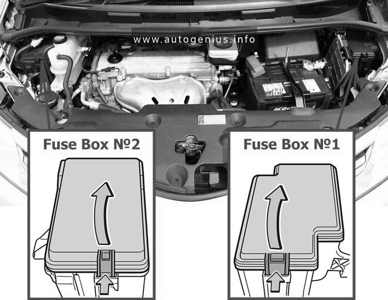
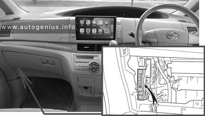
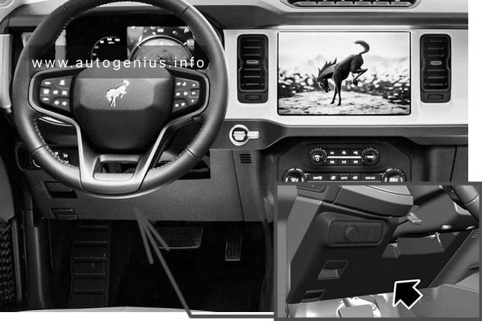
Fuse Box Location
The interior fuse block is located in instrument panel.
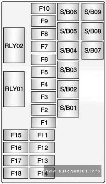
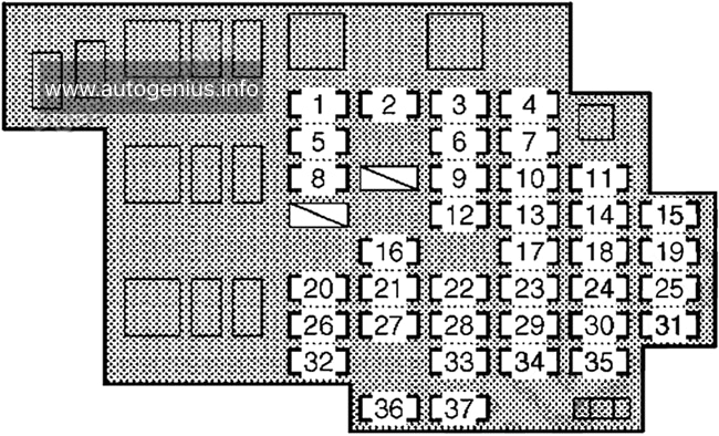
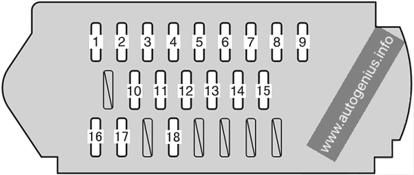
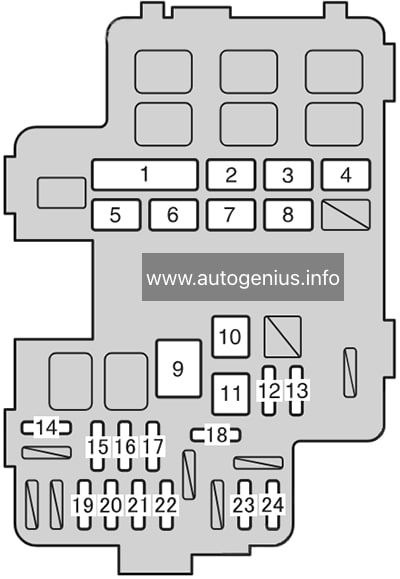
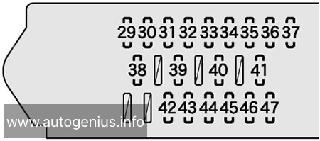
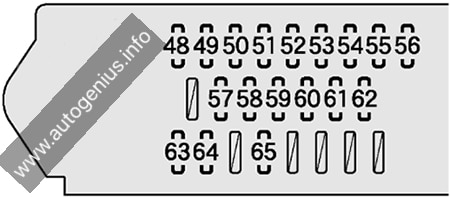
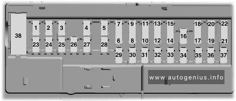
Fuse Box Diagram (Fuse Panel C)

Assignment of the fuses in the passenger compartment (instrument panel)
| № | A | Function / Component |
|---|---|---|
| F1 | – | – |
| F2 | 30A | Rear fresh air blower control module |
| F3 | 25A | Towing Recognition Control Module |
| F4 | – | – |
| F5 | 25A | Parking Lock Actuator |
| F6 | 30A | Vehicle Electrical System Control Module |
| F7 | 30A | Heater and A/C Controls |
| F8 | 20A | Sunroof Control Module |
| F9 | 30A | Driver Door Control Module Left Rear Door Control Module |
| F10 | – | – |
| F11 | 15A | Towing Recognition Control Module |
| F12 | 40A | Vehicle Electrical System Control Module |
| F13 | 40A | Vehicle Electrical System Control Module |
| F14 | 40A | Digital Sound System Control Module |
| F15 | – | – |
| F16 | 7.5A | Airbag Control Module |
| F17 | – | – |
| F18 | 7.5A | Access/Start System Interface Burglary Protection Control Module 2 Burglary Protection Control Module 3 Burglary Protection Control Module 4 Burglary Protection Control Module 5 Electronic Steering Column Lock Control Module |
| F19 | 7.5A | Instrument Cluster Control Module for Emergency Call Module and Communication Unit |
| F20 | 7.5A/15A | Storage Compartment with Cell Phone Interface USB Connection 1 USB Charging Socket 1 USB Charging Socket 2 Third Row Seat Left USB Charging Socket |
| F21 | 7.5A | Lane Change Assistance Control Module Lane Change Assistance Control Module 2 Rear Lid Opener Control Module Peripheral Camera Control Module Rear Lid Handle |
| F22 | – | – |
| F23 | – | – |
| F24 | 15A | All Wheel Drive Control Module |
| F25 | – | – |
| F26 | 30A | ‘front Passenger Door Control Module Right Rear Door Control Module |
| F27 | – | – |
| F28 | – | – |
| F29 | 15A | Towing Recognition Control Module |
| F30 | 30A | Information Electronics Control Module 1 |
| F31 | 25A | Towing Recognition Control Module |
| F32 | 25A | Rear A/C Display Control Head |
| F33 | – | – |
| F34 | 30A | Converter with Socket, 12V-230V |
| F35 | 40A | Vehicle Electrical System Control Module |
| F36 | 40A | Fresh Air Blower Control Module |
| F37 | 30A | Rear Lid Control Module |
| F38 | – | – |
| F39 | – | – |
| F40 | 7.5A | Alarm Horn |
| F41 | – | – |
| F42 | 7.5A | Selector mechanism Selector Lever Transmission Range Display |
| F43 | 10A | Vehicle Interior Temperature Sensor Heater and A/C Controls Tire Pressure Monitoring Control Module Rear A/C Display Control Head Rear Window Defogger Relay |
| F44 | 7.5A | Parking brake button Diagnostic Connection Front Roof Module Anti-Theft Alarm System Sensor Illumination Control Head Switch Module in Instrument Panel, Center Cornering Lamp and Headlamp Range Control Module Rain/Light Recognition Sensor |
| F45 | 7.5A | Steering Column Electronics Control Module |
| F46 | 7.5A | Windshield Projection Head Up Display Control Module Front Information Display Control Head |
| F47 | – | |
| F48 | 10A/7.5A | USB Charging Socket 1 USB Charging Socket 2 Third Row Seat Left USB Charging Socket USB Charging Socket in Headliner |
| F49 | – | – |
| F50 | – | – |
| F51 | – | – |
| F52 | 20A | 12 V Socket |
| F53 | – | – |
| F54 | – | – |
| F55 | – | – |
| F56 | – | – |
| F57 | – | – |
| F58 | 7.5A | Driver Assistance Systems Front Camera Parking Aid Control Module Control Module for Adaptive Cruise Control |
| F59 | 7.5A | Structure-Borne Sound Control Module Automatic Dimming Interior Rearview Mirror Air Quality Sensor Refrigerant Circuit Pressure Sensor Sockets Relay |
| F60 | 7.5A | Diagnostic Connection |
| F61 | 7.5A | Starter Relay 1 Starter Relay 2 |
| F62 | – | – |
| F63 | – | – |
| F64 | 7.5A | Passenger Occupant Detection System Control Module |
| F65 | – | – |
| F66 | 15A | Rear Window Wiper Motor |
| F67 | 30A | AM Frequency Filter |
| R1 | Sockets Relay | |
| R2 | Terminal 15 Power Supply Relay | |
| R3 | Rear Window Defogger Relay |
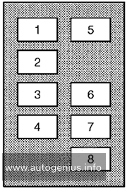
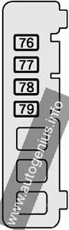
Individual Fuses
Fuse Box Diagram and Location
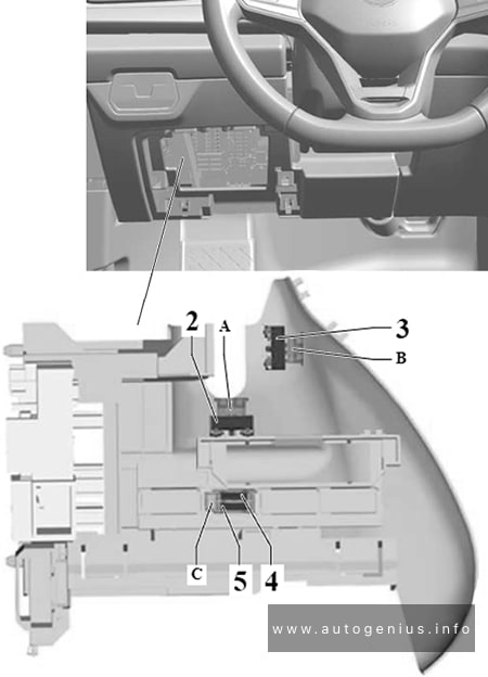
Assignment of the fuses in the individual fuses
| № | A | Function / Component |
|---|---|---|
| A | 15A | Driver Seat Adjustment Control Module (Driver memory seat) Driver Seat Lumbar Support Adjustment Switch (For vehicles with seat adjustment) Left Front Seat Backrest Fan 1 (For vehicles with seat ventilation) Left Front Seat Cushion Fan 1 (For vehicles with seat ventilation) |
| B | 15A | Right Front Seat Adjustment Control Head (Driver memory seat) Right Front Seat Backrest Fan 1 (For vehicles with seat ventilation) Right Front Seat Cushion Fan 1 (For vehicles with seat ventilation) |
| C | 30A | Electric Trailer Brake Position Sensor (For vehicles with trailer hitch) |
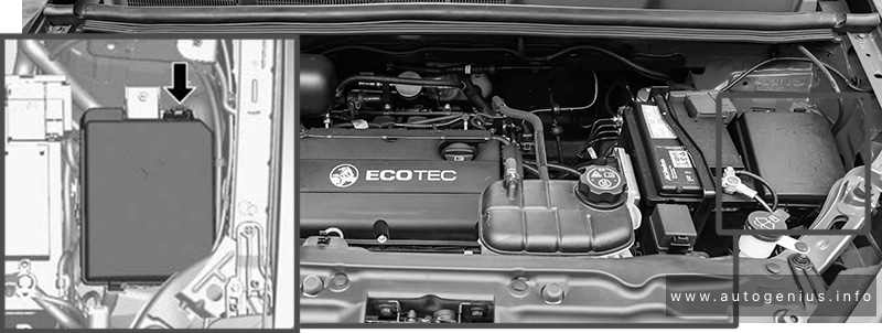
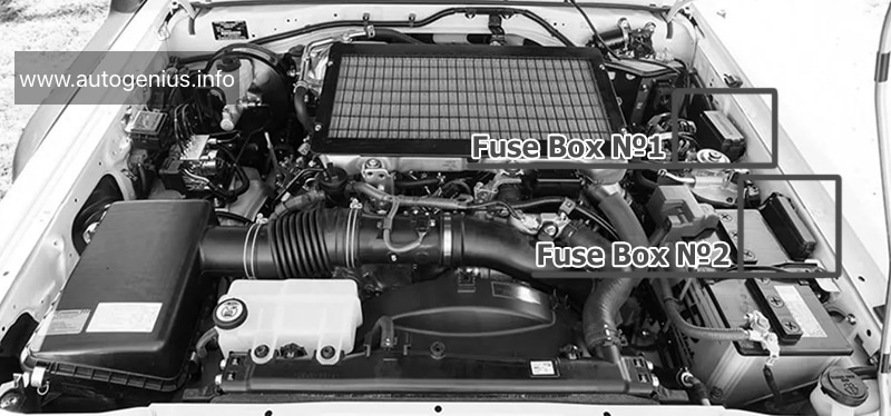
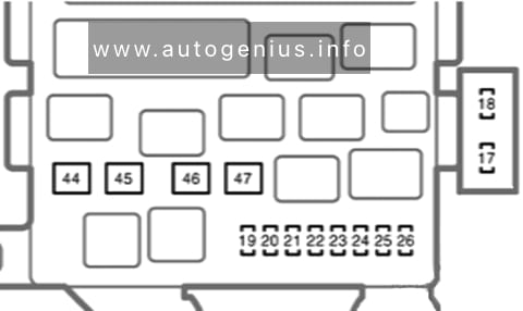
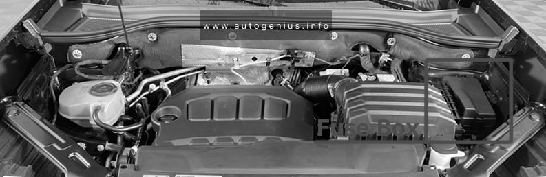
Engine Compartment Fuse Box
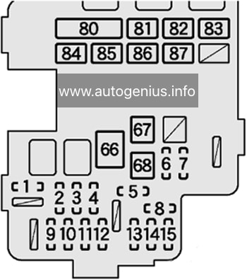
Fuse Box Location (Fuse Panel B)
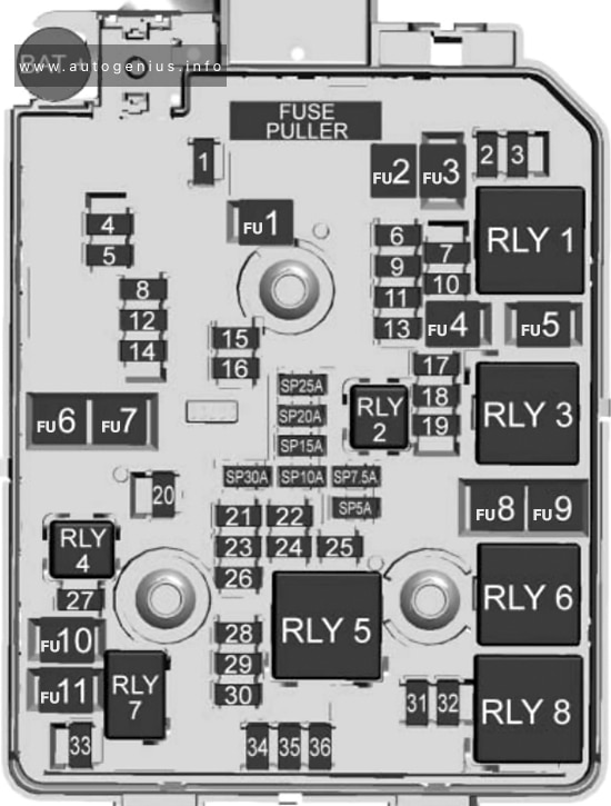
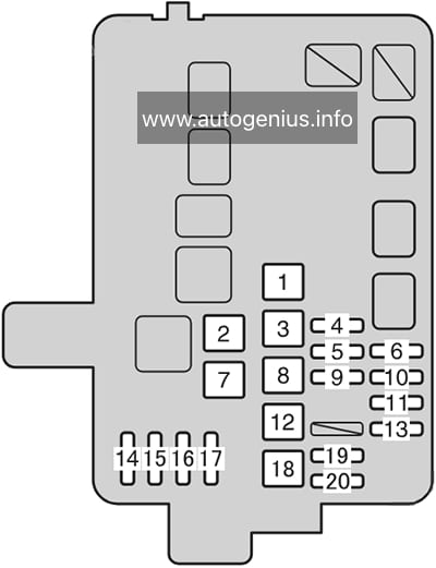
Fuse Box Diagram (Fuse Panel B)
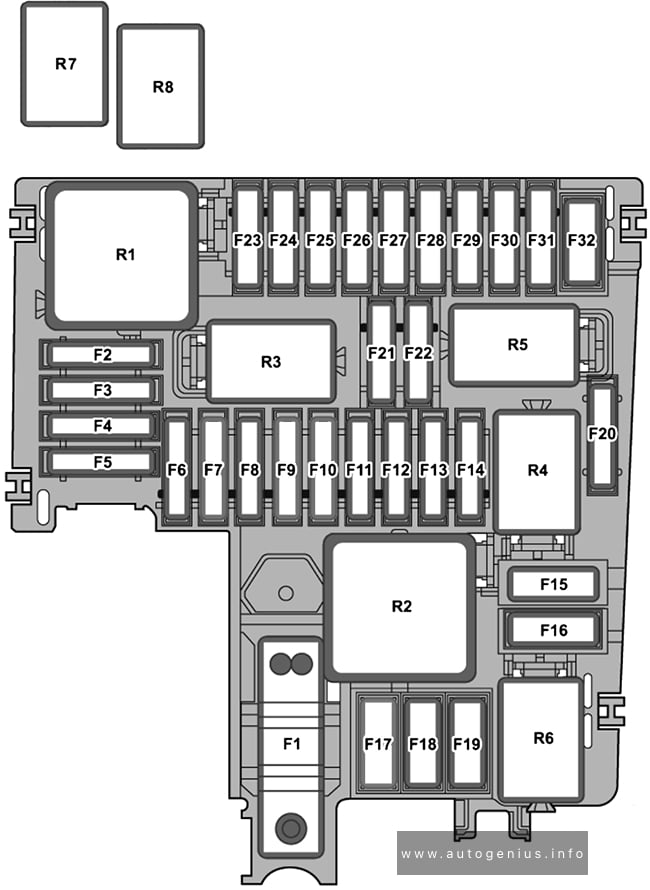
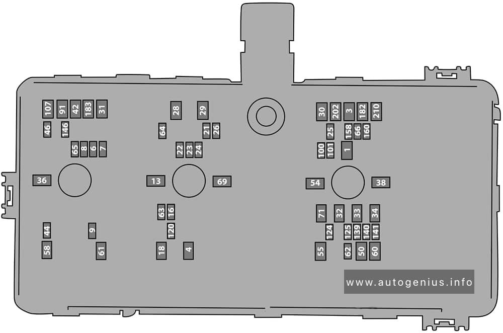
Assignment of the fuses in the engine compartment
| № | A | Function / Component |
|---|---|---|
| F1 | 100A | Power Steering Control Module |
| F2 | 7.5A | Engine/Motor Control Module ABS Control Module |
| F3 | 20A | Engine Component Power Supply Relay |
| F4 | 15A | Left Front Headlamp |
| F5 | 15A | Right Front Headlamp |
| F6 | – | – |
| F7 | – | – |
| F8 | – | – |
| F9 | 15A | Horn Relay |
| F10 | 30A | Wiper motor relay 1 Wiper motor relay 2 |
| F11 | – | – |
| F12 | 15A | Transmission Control Module |
| F13 | 25A | ABS Control Module |
| F14 | – | |
| F15 | 60A | ABS Control Module |
| F16 | – | – |
| F17 | – | – |
| F18 | – | – |
| F19 | – | – |
| F20 | – | – |
| F21 | 7.5A | Vehicle Electrical System Control Module |
| F22 | 30A | Starter |
| F23 | 15A | Vehicle Electrical System Control Module |
| F24 | 10A | Radiator Fan Engine Component Power Supply Relay EVAP Canister Purge Regulator Valve 1 Intake Manifold Runner Control Valve Camshaft Adjustment Valve 1 Turbocharger Recirculation Valve Oil Level Thermal Sensor Intake Manifold Runner Control Valve Oil Pressure Regulation Valve Piston Cooling Nozzle Control Valve |
| F25 | 10A | Cam adjustment actuator 1~8 |
| F26 | 10A | Radiator Shutter Motor Transmission Coolant Valve Fuel Tank Leak Detection Module Coolant Recirculation Pump |
| F27 | 10A | Oxygen Sensor 1 After Catalytic Converter Oxygen Sensor 1 Before Catalytic Converter |
| F28 | – | – |
| F29 | 10A | Fuel Pump Control Module |
| F30 | – | – |
| F31 | 7.5A | Brake Lamp Switch |
| F32 | – | – |
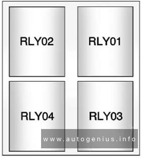
| R1 | Motronic Engine Control Module Power Supply Relay | |
| R2 | – | |
| R3 | Horn Relay | |
| R4 | Starter Relay 1 | |
| R5 | Starter Relay 2 | |
| R6 | Engine Component Power Supply Relay | |
| R7 | Wiper motor relay 1 | |
| R8 | Wiper motor relay 2 |
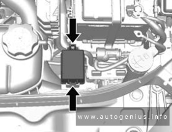
Fuse Panel A
Fuse Panel Location and Diagram
The main fuses are located on the battery. The multi-fuse must be replaced as a complete unit.
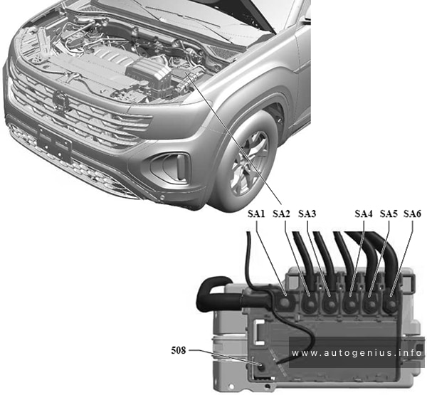
Assignment of the fuses in the fuse panel A
| № | A | Function / Component |
|---|---|---|
| SA1 | 400A | Generator with Voltage Regulator |
| SA2 | – | – |
| SA3 | 100A | Radiator Fan |
| SA4 | 125A | Fuse Panel C (Instrument Panel): Fuses 2, 3, 5, 6, 7, 8, 9, 11, 12, 13, 14, 16, 19, 20, 21, 24. |
| SA5 | 125A | Fuse Panel C (Instrument Panel): Fuses 26, 29, 30, 31, 32, 34, 35, 36, 37, 40, 42, 43, 44, 45, 46, 48, 52, 58, 59, 60, 61, 64, 66, 67. Sockets Relay Terminal 15 Power Supply Relay Rear Window Defogger Relay |
| SA6 | 150A | Fuse Panel B (Engine Compartment): Fuses 1, 2, 3, 4, 5, 9, 10, 12, 13, 15, 21, 22, 23, 24, 25, 26, 27, 29, 31. Horn Relay Motronic Engine Control Module Power Supply Relay Starter Relay 1 Starter Relay 2 Engine Component Power Supply Relay |
WARNING: Terminal and harness assignments for individual connectors will vary depending on vehicle equipment level, model, and market.