RAM 1500 (2019 – 2021) – fuse and relay box diagram
Year of production: 2019, 2020, 2021
The Dodge Ram 1500 (2019–2021) represents the fifth generation of the Ram truck lineup and is renowned for its blend of rugged capability, modern technology, and refined design. In 2019, the Ram 1500 received a significant overhaul, making it more comfortable, capable, and technologically advanced, which helped it stand out in the highly competitive full-size pickup truck market against rivals like the Ford F-150 and Chevrolet Silverado.
Internal Power Distribution Center
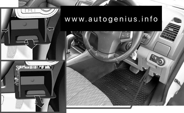
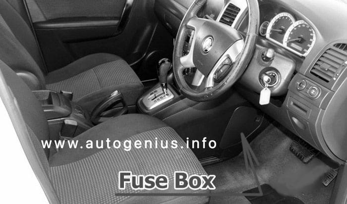
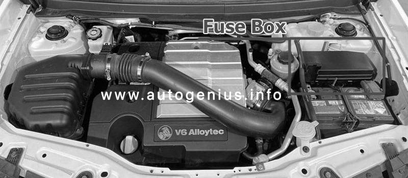
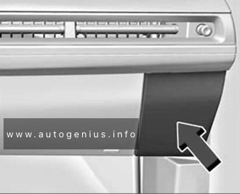
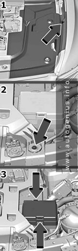
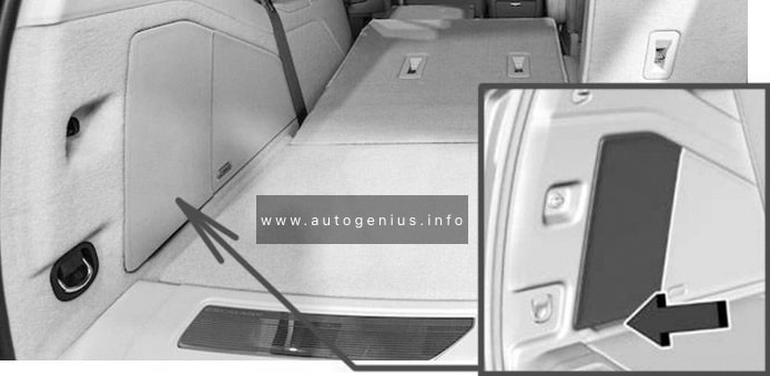
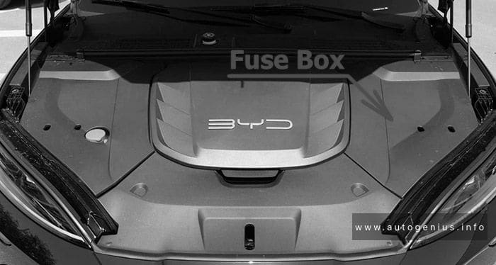
Fuse Box Location
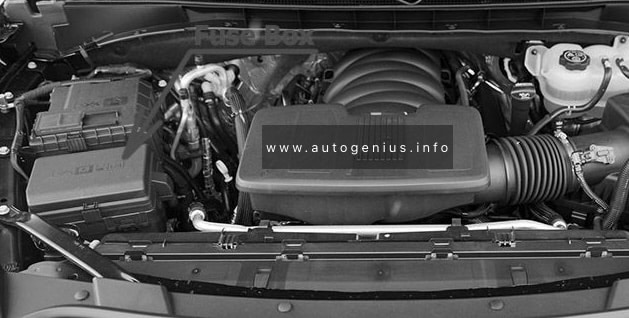
The Power Distribution Center is located in the engine compartment near the battery. This center contains cartridge fuses, micro fuses, relays, and circuit breakers.
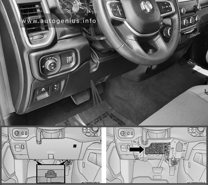
For access:
- Locate and remove the two screws from the lower portion of the fuse panel cover.
- After removing the screws, gently pull both the left and right side of the fuse panel cover to release the fastener clips.
- Reverse the procedure to reinstall the fuse panel cover.
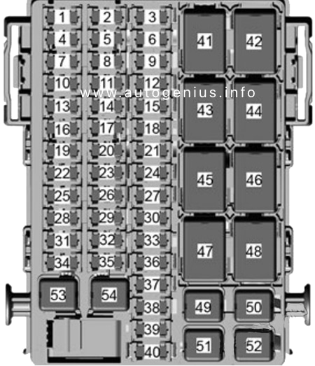
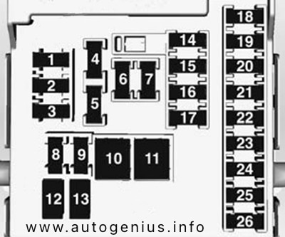
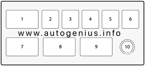
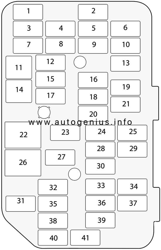
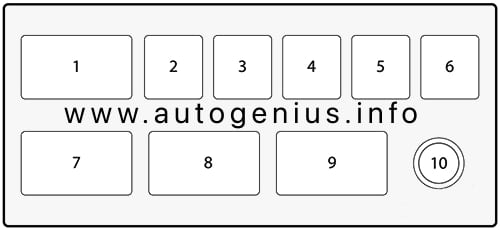
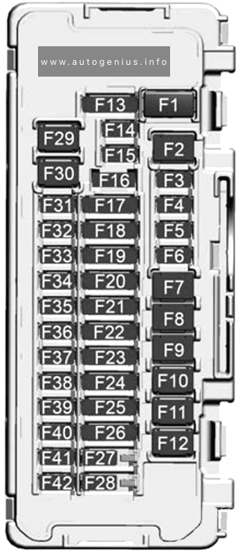
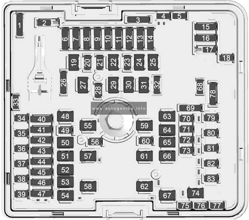
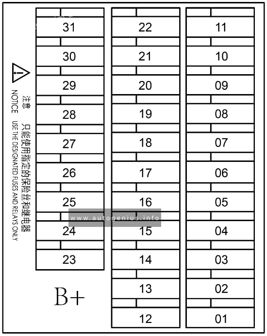
Fuse Box Diagram
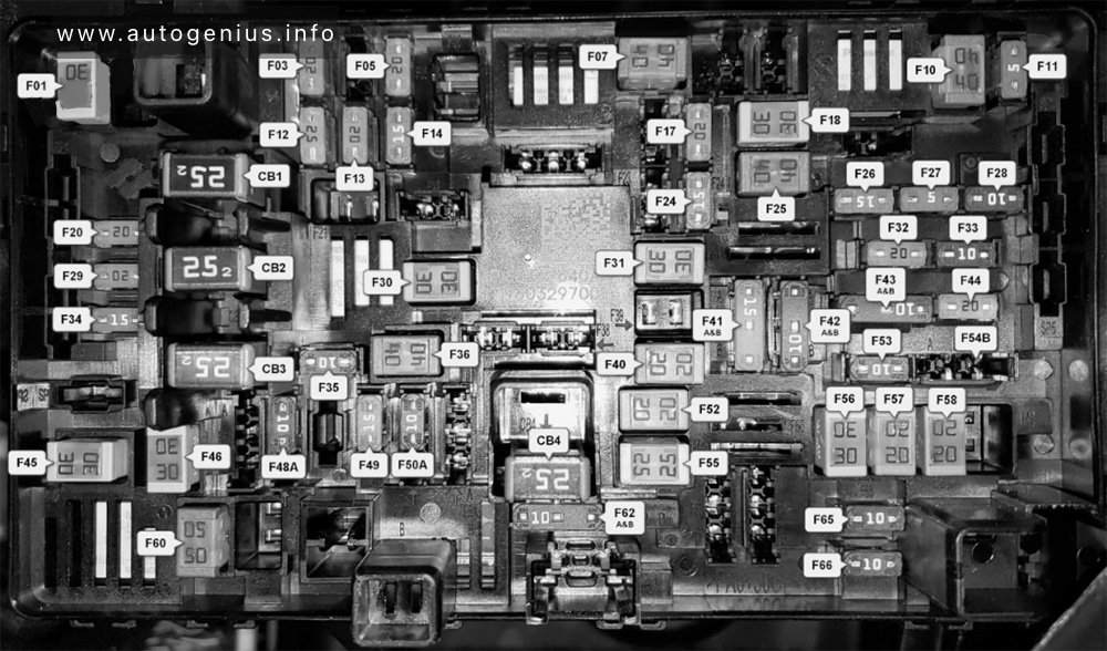
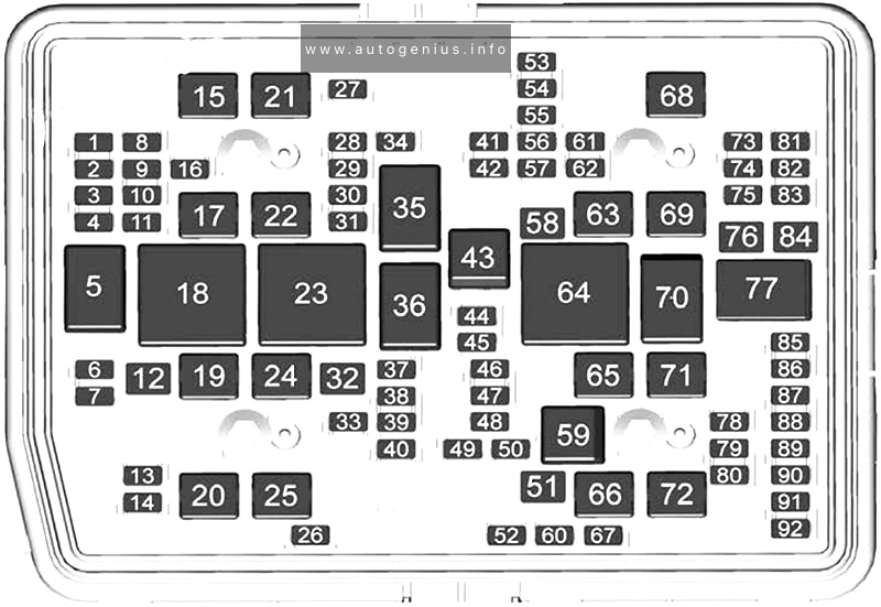
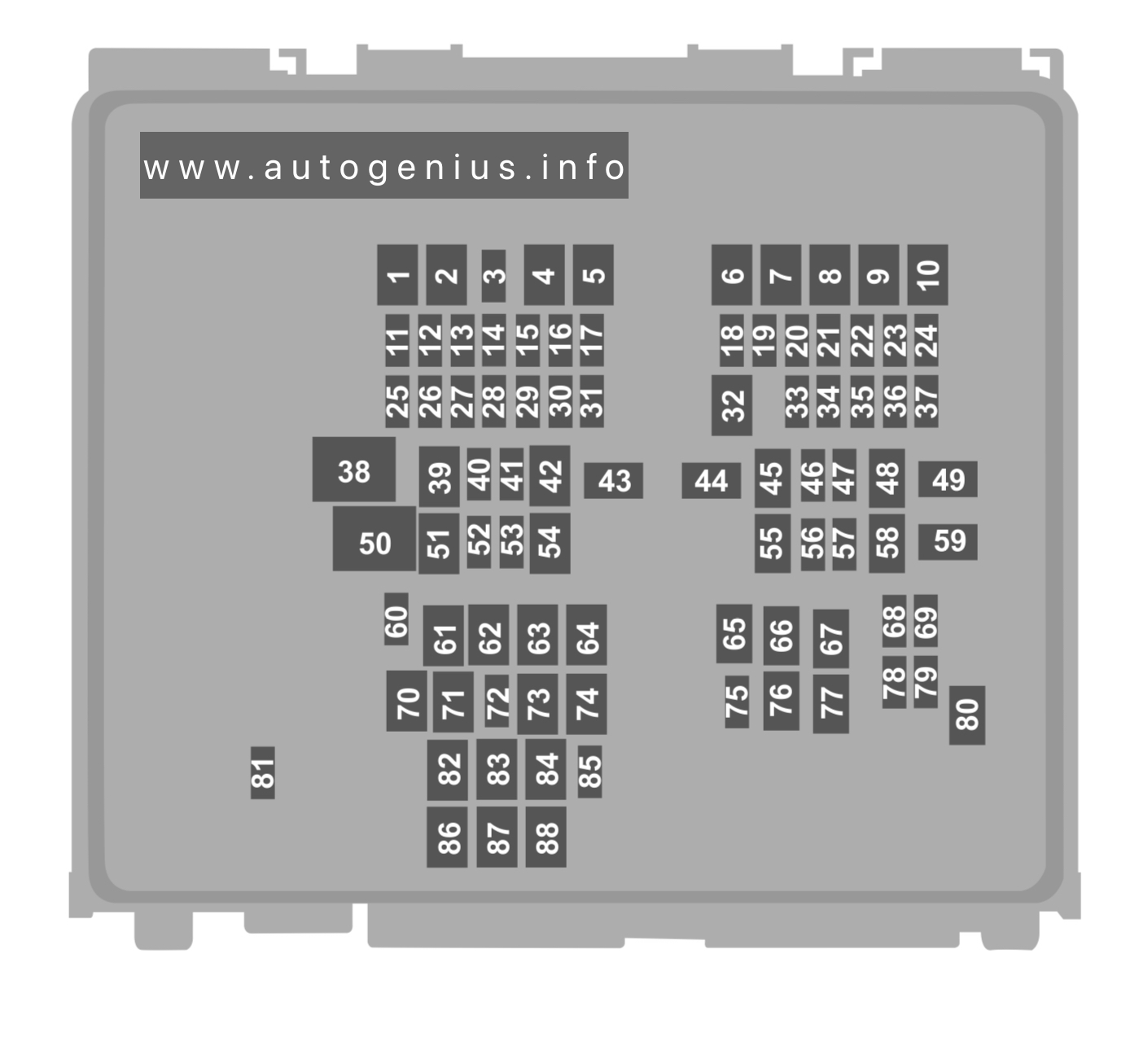
Assignment of the fuses in the instrument panel fuse box (2019-2021)
| № | Amps | Description |
|---|---|---|
| F01 | 30 | Trailer Tow Receptacle |
| F02 | – | Spare |
| F03 | 20 | Seat Heater Module – Front Passenger |
| F04 | – | Spare |
| F05 | 20 | eToraue Power Pack Unit (PPU) Cooling Fan Module |
| F06 | – | Spare |
| F07 | 40 | Central Body Controller (CBC) 3 Power Locks Module |
| F08 | – | Spare |
| F09 | – | Spare |
| F10 | 40 | Heating Ventilation and Air Conditioning (HVAC) Blower Motor |
| F11 | 5 | Output to Under-Hood Power Distribution Center (UPDC) Run Coil |
| F12 | 25 | Audio Amplifier Module / Active Noise Cancellation (ANC) / Sine Wave (SW) Inverter |
| F13 | 20 | Seat Heater Module – Driver |
| F14 | 15 | Steering Wheel Heater Module |
| F15 | – | Spare |
| F16 | – | Spare |
| F17 | 20 | Left Spot Lamp – If Equipped |
| F18 | 30 | Sunshade Sunroof Motor |
| F19 | – | Spare |
| F20 | 20 | Comfort Rear Seat Module (CRSM) (Heat Rear Right) |
| F21 | – | Spare |
| F22 | – | Spare |
| F23 | – | Spare |
| F24 | 15 | Radio Frequency (RF) Hub Module / Ignition Module / Cluster Module |
| F25 | 40 | Integrated Trailer Brake Module |
| F26 | 15 | Cluster Cabin/Compartment Node (CCN) Module / Cyber Security Module |
| F27 | 5 | Cluster Cabin/Compartment Node (CCN) Module / Secure Gateway (SGW) Module |
| F28 | 10 | Occupant Restraint Control (ORC) Module |
| F29 | 20 | Comfort Rear Seat Module (CRSM) (Heat Rear Left) |
| F30 | 30 | Drive Train Controller Module (DTCM) / Tailgate Module |
| F31 | 30 | Central Body Controller (CBC) 1 Interior Light Module |
| F32 | 20 | Right Spot Lamp – If Equipped |
| F33 | 10 | Overhead Console / 911 Switch / Assist Switch / Heads Up Display (HUD) |
| F34 | 15 | Front & Rear Ventilated Seat Motor |
| F35 | 10 | Inverter Module / Sunshade Sunroof Motor / Dual Sunroof Motor / USB Charge Only |
| F36 | 40 | Central Body Controller (CBC) 2 Exterior Light 1 |
| F37 | – | Spare |
| F38 | – | Spare |
| F39 | – | Spare |
| F40 | 20 | Dome Pursuit Vehicle — If Equipped |
| F41A / F41B | 15 | Lumbar Support & Pass Switch / Integrated Center Stack (ICS) Switch Bank Module / HVAC Ctrl / Bank Upper Switch / Steering Control Module |
| F42A / F42B | 10 | Transfer Case Switch Module (TCSM) / Shift bv Wire Module (SBW) / Electric Park Brake Switch / Overhead Console (OHC) Switch / E-Call / Bank 3 Switch / Seat Left & Riaht Ventilation / Trailer A&B Tire Pressure Module / Gateway Trailer Module |
| F43A / F43B | 10 | Port Diagnostics / Collision Detection (CD) Module / Front & Rear USB |
| F44 | 20 | Radio/Digital Content Service Delivery (DCSD) Module / Telematics Box Module/Fleet Telematics Module (FTM) |
| F45 | 30 | Door Multiplexer Module (Driver-side) |
| F46 | 30 | Door Multiplexer Module (Passenger-side) |
| F47 | – | Spare |
| F48A | 10 | Rear View Mirror / SW Window Passenger / Rear USB / Wireless Charging Pad Module |
| F49 | 15 | Central Vision Processing Module (CVPM) / Sensor Blind SDot / HDLP AdaDtive Front Lighting Sensor (AFLS) |
| F50A | 10 | Battery Pack Control Module |
| F51A / F51B | – | Spare |
| F52 | 20 | Direct Battery Feed – If Equipped |
| F53 | 10 | Trailer Reverse Steerina Control / Trailer Steerinq Control Knob |
| F54B | 20 | Power Outlet Center Seat |
| F55 | 25 | Upfitter – If Equipped |
| F56 | 30 | Network Interface Module – If Equipped |
| F57 | 20 | Direct Battery Feed – If Equipped |
| F58 | 20 | Direct Battery Feed – If Equipped |
| F59 | – | Spare |
| F60 | 50 | Inverter Module |
| F61 | – | Spare |
| F62A / F62B | 10 | Intearated T railer Brakina (ITBM) / Occupant Class Mod / IAIR Suspension Mod / HVAC Sensor In-Car Temp Module / Rear Coolant Temp / Parktronic System (PTS) / Intearated Relay Ctrl Mod (IRCM) / HRLS / Gateway Trailer TPMS Module |
| F63 | – | Spare |
| F64 | – | Spare |
| F65 | 10 | Occupant Restraint Controller (ORC) Module |
| F66 | 10 | Run Accessory Feed — If Equipped |
| CB1 | 25 | Driver Window SW Rear PWR Windows / Overhead SW Rear Defrost |
| CB2 | 25 | Driver PWR Seat / Driver Seat Memory Mod |
| CB3 | 25 | Passenger Power Seat / Passenger Seat Memory Mod |
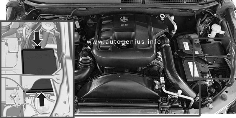
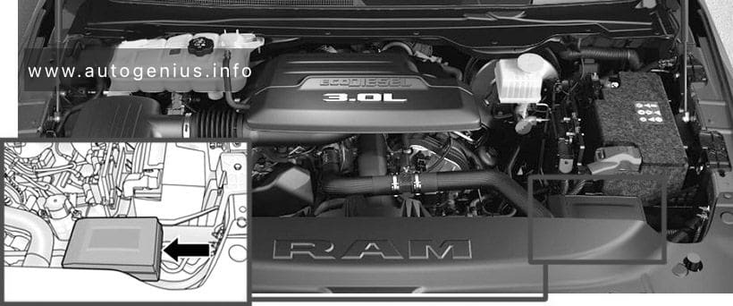
External Power Distribution Center
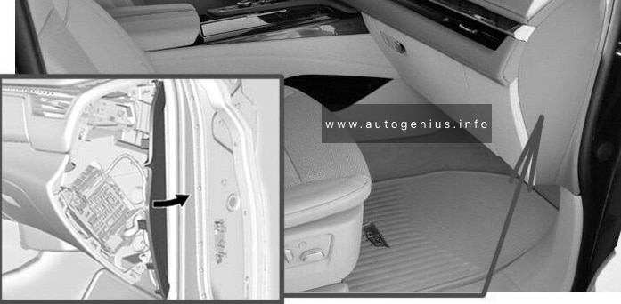
Fuse Box Location
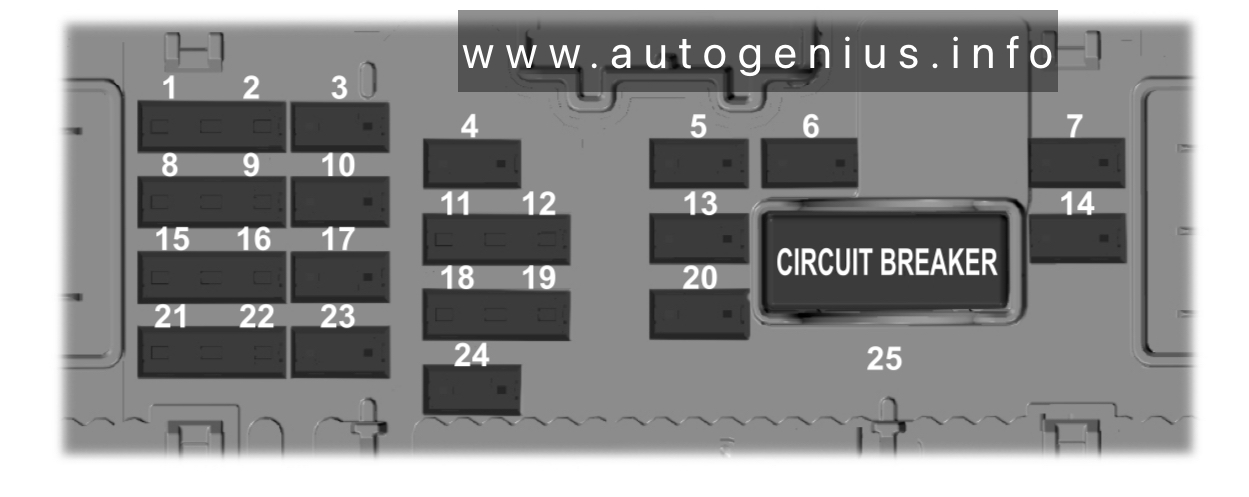
The Power Distribution Center is located in the engine compartment near the battery. This center contains cartridge fuses, micro fuses, relays, and circuit breakers. A description of each fuse and component may be stamped on the inside cover, otherwise the cavity number of each fuse is stamped on the inside cover that corresponds to the following chart.
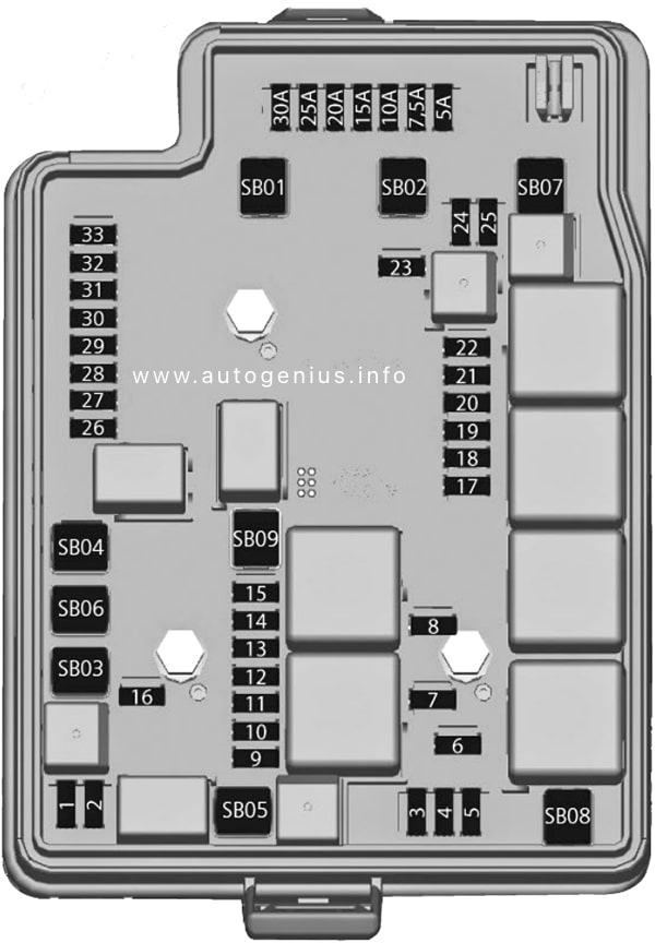
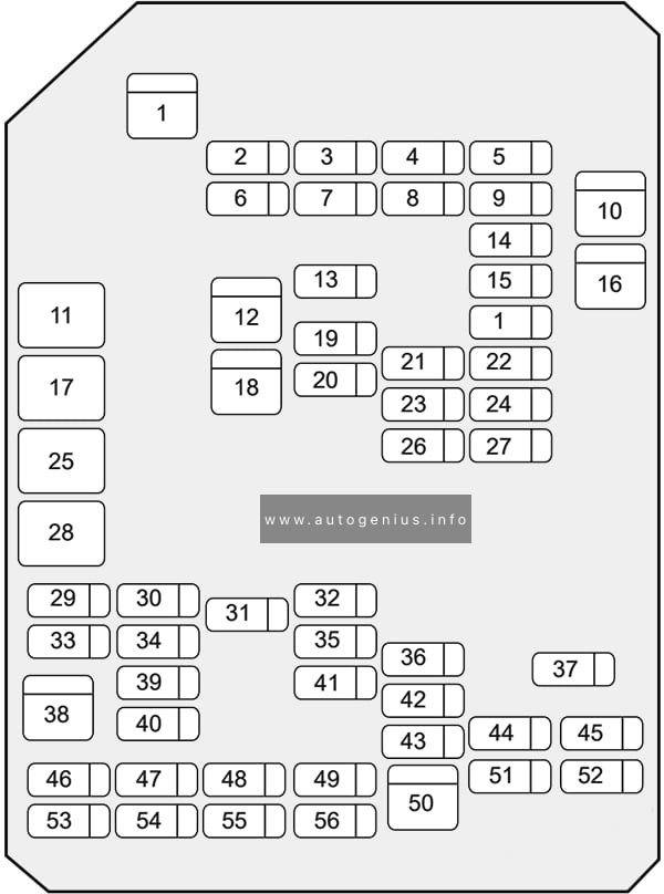
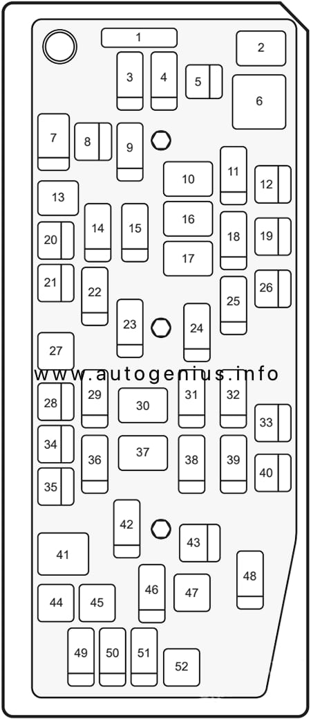
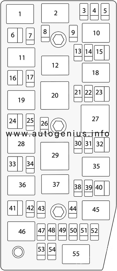
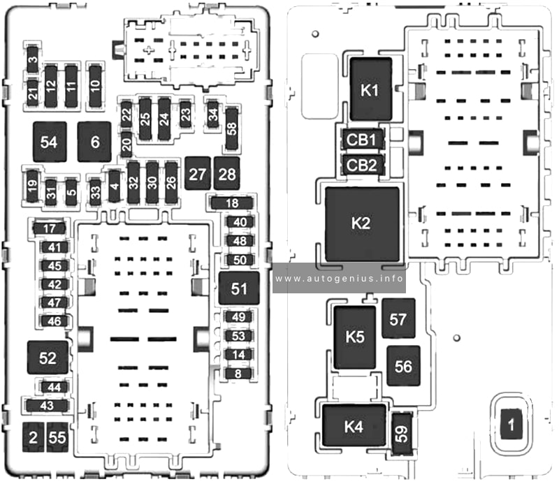
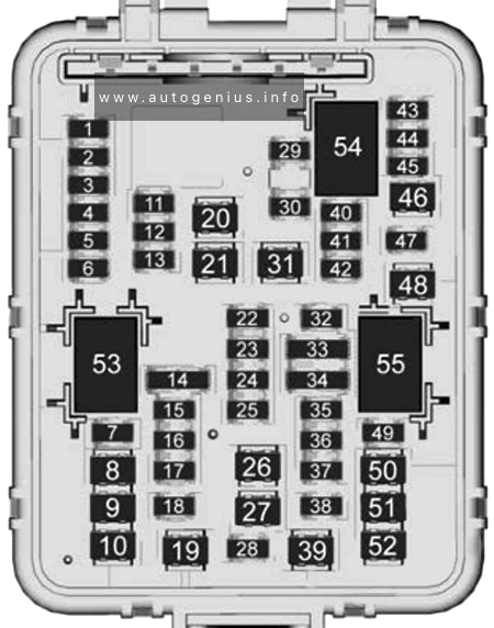
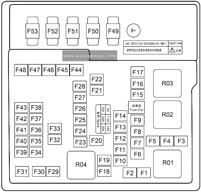
Fuse Box Diagram
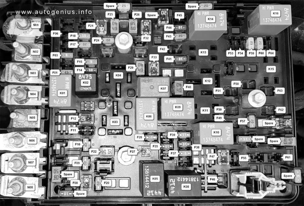
Assignment of the fuses in the engine compartment fuse box (2019-2021)
| № | Amps | Description |
|---|---|---|
| F01 | 25 | Fuel Pump Motor |
| F02 | – | Spare |
| F03 | 5 | eTorque Motor Generator Unit (MGU) |
| F04 | – | Spare |
| F05 | – | Spare |
| F06 | 10 | Output to Upfitter Power Distribution Center (PDC) – If Equipped |
| F07 | – | Spare |
| F08 | 20 | Trailer Tow Backup Lamp |
| F09 | 20 | Trailer Stop / Turn Lamp Left |
| F10 | 20 | Trailer Stop / Turn Lamp Right |
| F11 | 15 | ID/Clearance Lights – If Equipped |
| F12 | 20 | Trailer Tow Park Lamp |
| F13 | – | Spare |
| F14 | 10 | Air Conditioner (AC) Clutch |
| F15 | 5 | Intelligent Battery Sensor (IBS) |
| F16 | – | Active Damping Control Module (ADCM) |
| F17 | 20 | Air Suspension |
| F18 | 15 | Active Grill Shutter (AGS) / Rear Axle Cooling Valve / Active Air Dam |
| F19 | – | Spare |
| F20 | 20 | Adjustable Pedals |
| F21 | 30 | Power Side Step |
| F22 | 50 | Air Suspension Control Module |
| F23 | – | Spare |
| F24 | 20 | Transmission Control Module (TCM). Shift by Wire Module (SBW) |
| F25 | 40 | Exterior Lights 2 |
| F26 | 50 | Electronic Stability Program (ESP) Module |
| F27 | 30 | Front Wiper |
| F28 | 10 | Powertrain Control Module (PCM) / Electronic Control Module (ECM) |
| F29 | 40 | Electronic Stability Program (ESP) Module |
| F30 | – | Spare |
| F31 | – | Spare |
| F32 | 20 | Electronic Control Module (ECM) / Powertrain Control Module (PCM) |
| F33 | 30 | Brake Vacuum Pump |
| F34 | – | Spare |
| F35 | 10 | Electronic Control Module (ECM) / Powertrain Control Module (PCM) / eTorque Power Pack Unit (PPU) Motor Generator Unit (MGU) / Wake Up / Electric Power Steering / Active Tuned Mass Module (ATMM) / ESP |
| F36 | – | Spare |
| F37 | 5 | Run/Start (R/S) Switch Output to Internal Power Distribution Center (IPDC) |
| F38 | 10 | Drive Train Controller Module (DTCM) / Active Cooling Temperature Valve |
| F39 | 15 | Active Tuned Mass Module (ATMM) |
| F40 | 40 | Starter |
| F41 | 10 | Infrared Camera (IRCAM) Heaters |
| F42 | 20 | Auxiliary Switch #5 – If Equipped |
| F43 | 20 | Motor Generator Unit (MGU) Coolant Pump |
| F44 | 10 | Trailer Camera |
| F45 | 10 | Active Damping Control Module (ADCM) – If Equipped |
| F46 | 30 | Fuel Heater (Diesel Only) |
| F47 | 30 | Rear Defroster |
| F48 | – | Spare |
| F49 | 30 | Heater Control (Diesel Only) |
| F50 | 20 | Auxiliary Switch #6 – If Equipped |
| F51 | 25 | Fuel Pump Motor #1 – If Equipped |
| F52 | – | Spare |
| F53 | 10 | Supply / Purging Pump – If Equipped |
| F54 | 15 | Powertrain Control Module (PCM) |
| F55 | 15 | Right High-Intensity Discharge (HID) Headlamp |
| F56 | – | Spare |
| F57 | 20 | Horn |
| F58 | 25 | Fuel Pump Motor #2 – If Equipped |
| F59 | 25 | Injectors / Ignition (IGN) Coil / Glow Plug Module |
| F60 | 20 | Electronic Control Module (ECM) / Powertrain Control Module (PCM) / Actuator (ACT) Short Running Valve |
| F61 | 15 | Left High-Intensity Discharge (HID) Headlamp / Spare |
| F62 | 60 | Glow Plug (Diesel) |
| F62 | 40 | Low Temperature Radiator (LTR) Cooling Pump (TRX only) |
| F63 | 20 | Diesel Nitrogen Oxide (NOx) Sensor (Diesel) |
| F64 | 10 | Particulate Matter (PM) Sensor – If Equipped (Diesel) |
| High Current Fuses | ||
| N01 | BUS | B+ BUS Feed |
| N02 | – | Spare |
| N03 | 80 | Internal Power Distribution Center (IPDC) Feed 1 |
| N04 | 80 | Internal Power Distribution Center (IPDC) Feed 2 |
| N05 | 150 | Auxiliary Power Distribution Center (PDC) |
| N06 | 300 | Power Pack Unit (PPU) Generator – eTorque |
| N07 | 80 | Electric Power Steering (EPS) |
| N08 | 100 | Radiator Fan |
| Relays | ||
| K01 | Fuel Pump | |
| K02 | Air Conditioner Clutch | |
| K03 | Spare | |
| K04 | Spare | |
| K05 | Front Wiper Control | |
| K06 | Starter # 2 | |
| K07 | Brake Vacuum Pump | |
| K08 | Front Wiper Speed | |
| K09 | Starter #1 | |
| K10 | Run/Start #1 | |
| K11 | Auxiliary Switch # 6 – If Equipped | |
| K12 | Street and Racing Technology (SRT) Fuel Pump – If Equipped | |
| K13 | Auxiliary Switch # 5 – If Equipped | |
| K14 | Run Only #1 | |
| K15 | Selective Catalytic Reduction (SCR) #2 (Diesel) | |
| K16 | Automatic Shutdown (ASD) |
WARNING: Terminal and harness assignments for individual connectors will vary depending on vehicle equipment level, model, and market.