Chery Tiggo 7 (T15; 2016 – 2020) – fuse and relay box diagram
Year of production: 2016, 2017, 2018, 2019, 2020
Passenger Compartment Fuse Panel
Fuse Box Location
Instrument panel fuse and relay box is located on the lower left side of instrument panel.
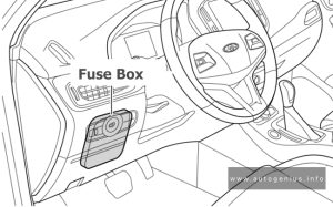
Fuse Box Diagram
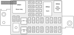
Assignment of the fuses in the instrument panel
| № | Description |
|---|---|
| RF01 | BCM |
| RF02 | – |
| RF03 | Steering Wheel Rotation Angle Sensor, EPS |
| RF04 | Main Blind Spot Monitor Radar, Auxiliary Blind Spot Monitor Radar |
| RF05 | Airbag Module |
| RF06 | – |
| RF07 | A/C Wire Harness Interface, Audio Head Unit, Automatic A/C Panel, Headlight Adjustment Switch, DCT Shift Mechanism |
| RF08 | – |
| RF09 | A/C Wire Harness Interface, Audio Head Unit, Audio Head Unit, Automatic A/C Panel |
| RF10 | Instrument Cluster, Rain Sensor |
| RF11 | – |
| RF12 | – |
| RF13 | – |
| RF14 | – |
| RF15 | Around View Monitor |
| RF16 | – |
| RF17 | – |
| RF18 | A/C Panel, Left/Right Outside Rear View Mirror, A/C Wire Harness Interface |
| RF19 | – |
| RF20 | Power Supply of Blower Relay Output Terminal |
| RF21 | – |
| RF22 | – |
| RF23 | – |
| RF24 | Power Supply of Rear DEF Relay Output Terminal |
| RF25 | – |
| RF26 | Mirror Adjustment Switch, BCM, Sunroof |
| RF27 | Cigarette Lighter |
| RF28 | – |
Engine Compartment Fuse Box
Fuse Box Location
The fuse box is located on the left side of engine compartment and the rear side of left headlight.
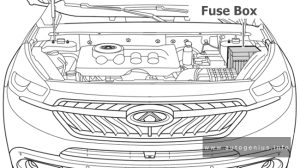
Fuse Box Diagram
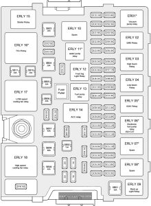
Assignment of the fuses in the engine compartment
| № | Description |
|---|---|
| SB01 | Reserve |
| SB02 | ACC |
| SB03 | Starter/drive chain |
| SB04 | TCU/DCT |
| SB05 | BCM 2 |
| SB06 | BCM 1 |
| SB07 | ESP/ABS |
| SB08 | EPB |
| SB09 | ACM/EPB |
| SB10 | ESP/ABS |
| SB11 | Seat adjustment SEAT |
| EF01 | Vacuum pump |
| EF02 | Oxygen sensor |
| EF03 | Ignition coil 3 |
| EF04 | ECU solenoid valve |
| EF05 | PPD& HVH |
| EF06 | Reserve |
| EF07 | Right headlight high beam |
| EF08 | Left headlight low beam |
| EF09 | Reserve |
| EF10 | ECU & fan controller with hybrid system |
| EF11 | PEPS |
| EF12 | LT & PTC water pump |
| EF13 | ECU & TCU brake switch 15+ Sreversing sensor & IPU with hybridsystem |
| EF14 | Inner mirror & A/C pressure switch& reversing radar |
| EF15 | PEPS & 4WD |
| EF16 | Electronic oil pump |
| EF17 | Reserve |
| EF18 | Back-up light |
| EF19 | Alternator excitation |
| EF20 | Injector |
| EF21 | Reserve |
| EF22 | Water pump |
| EF23 | POD & PPD & EAC |
| EF24 | Horn |
| EF25 | Left headlight high beam |
| EF26 | Right headlight low beam |
| EF27 | Front fog light |
| EF28 | ESP & ABS & ACM |
| EF29 | Fuel pump |
| EF30 | BCM 6 |
| EF31 | IGN 1 |
| EF32 | Brake switch & PEPS & DOT 30+ |
| EF33 | ACM |
| EF34 | BCM 5 |
| EF35 | BCM 3 |
| EF36 | Reserve |
| EF37 | Spare power 2 |
| EF38 | ECU & TCU 30+ |
| EF39 | Wiper |
| EF40 | 4WD & IPU |
| EF41 | Seat heating |
| EF42 | Air conditioning compressor |
| EF43 | Reserve |
| EF44 | BCM 4 |
| EF45 | Sunroof |
| EF46 | Marine insurance |
| EF51 | – |
Power fuses
Fuse Box Diagram
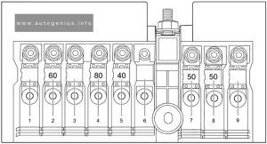
Assignment of the power fuses
| № | Amps | Description |
|---|---|---|
| 1 | – | – |
| 2 | 60A | Instrument Panel Fuse and Relay Box |
| 3 | – | – |
| 4 | 80A | EPS |
| 5 | 40A | Low-speed Cooling Fan |
| 6 | – | – |
| 7 | 150A | Alternator |
| 8 | 50A | High-speed Cooling Fan |
| 9 | – | – |
WARNING: Terminal and harness assignments for individual connectors will vary depending on vehicle equipment level, model, and market.
