Chery Tiggo 8 (T18; 2017 – 2020) – fuse and relay box diagram
Year of production: 2017, 2018, 2019, 2020
The Chery Tiggo 8 PRO, a mid-size crossover, has been available since 2020 and continues to be produced. In this guide, you’ll find fuse box diagrams for the 2020, 2021, 2022, and 2023 models. It also provides information on the location of the fuse panels inside the vehicle, along with details about the fuse assignments (fuse layout) and relays.
Passenger Compartment Fuse Panel
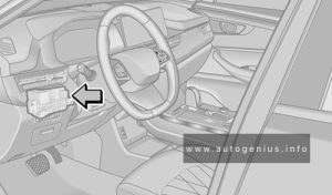
Fuse Box Location
The fuses are located on the lower left side of instrument panel.

Fuse Box Diagrams

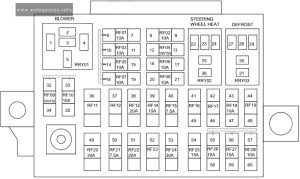
Assignment of the fuses in the instrument panel
| № | Description |
|---|---|
| RF01 | BCM & Instrument Cluster & Gateway |
| RF02 | – |
| RF03 | EPS & Angle Sensor |
| RF04 | Multi-View Camera System |
| RF05 | Airbag Module |
| RF06 | – |
| RF07 | A/C Control Panel & Radio Control Module & Head Lamps Adjust Sw Power & TBOX & Shift Lever (DCT) |
| RF08 | – |
| RF09 | A/C Control Panel & Radio Contrl Module & TBOX & DCDC |
| RF10 | Instrument Cluster |
| RF11 | – |
| RF12 | – |
| RF13 | – |
| RF14 | Tachograph |
| RF15 | Defrost Relay & EPB & Panoramic Image Module & OBD Diagnostic Interface & Sub-instrumentation Switch & Kick Wire Sensor |
| RF16 | – |
| RF17 | – |
| RF18 | A/C Control Panel & Defrost Work Feedback |
| RF19 | – |
| RF20 | Rry01 Blower RLY |
| RF21 | – |
| RF22 | – |
| RF23 | – |
| RF24 | Rry03 Defrost RLY |
| RF25 | – |
| RF26 | BCM & Radio & Power Rear View Mirror Switch |
| RF27 | Cigarette Lighter |
| RF28 | Spare Power |
Engine Compartment Fuse Box
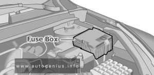
Fuse Box Location
The fuse box is located on the left side of engine compartment and the rear side of left headlight.

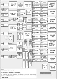
Fuse Box Diagram

Assignment of the fuses in the engine compartment
| № | Description |
|---|---|
| SB01 | ISS 1 |
| SB02 | ACC |
| SB03 | Start control |
| SB04 | Rear Blower |
| SB05 | BCM 2 |
| SB06 | BCM 1 |
| SB07 | ABS/EPS |
| SB08 | ESP (EPB) |
| SB09 | DCT |
| SB10 | PLG |
| SB11 | Seat adjustment |
| EF01 | ERLY 01 vacuum pump RLY |
| EF02 | Lambda sensor heating upstream & lambda sensor heating downstream |
| EF03 | Ignition coil |
| EF04 | ECU solenoid valve |
| EF05 | – |
| EF06 | AGS |
| EF07 | – |
| EF08 | Left Low beam power |
| EF09 | – |
| EF10 | ERLY 02 ECU RLY |
| EF11 | PEPS |
| EF12 | – |
| EF13 | ECU & DCT & brake SW |
| EF14 | AC & Sunroof & Reverse Radar Module |
| EF15 | PEPS & DC-DC (ISS) |
| EF16 | Rear Blower |
| EF17 | – |
| EF18 | – |
| EF19 | – |
| EF20 | Injector Cyl1.2.3.4 |
| EF21 | ISS 2 |
| EF22 | – |
| EF23 | – |
| EF24 | ERLY 20 High beam RLY |
| EF25 | – |
| EF26 | Right Low beam power |
| EF27 | ERLY 12 horn RLY |
| EF28 | ESP (EPB) |
| EF29 | ERLY13 fuel pump RLY |
| EF30 | BCM |
| EF31 | IGN (a) & IGN (b) |
| EF32 | PEPS & brake SW |
| EF33 | PLG |
| EF34 | BCM |
| EF35 | BCM |
| EF36 | – |
| EF37 | Spare Power |
| EF38 | ECU & DCT |
| EF39 | Wiper RLY |
| EF40 | – |
| EF41 | Seat Heater |
| EF42 | ERLY 19 AC clutch RLY |
| EF43 | – |
| EF44 | BCM |
| EF45 | Sunroof |
| EF46 | 30IP (b) & DC-DC (ISS) |
| EF47 | IP Fuse Box power |
| EF48 | EPS power |
| EF49 | ALT power |
| EF52 | ERLY 17 Low Fan RLY |
| EF53 | ERLY 18 High Fan RLY |
WARNING: Terminal and harness assignments for individual connectors will vary depending on vehicle equipment level, model, and market.
