Volkswagen Touareg (CR; 2018 – 2025) – fuse and relay box diagram
Year of production: 2018, 2019, 2020, 2021, 2022, 2023, 2024, 2025
The third-generation Volkswagen Touareg, with CR designations, was manufactured from 2018 through 2025. During this period, the model underwent a facelift. In this guide, we will provide an overview of the fuses and relays for the Volkswagen Touareg 3G, including fuse box diagrams, their locations.
Passenger compartment
Fuse box location
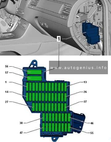
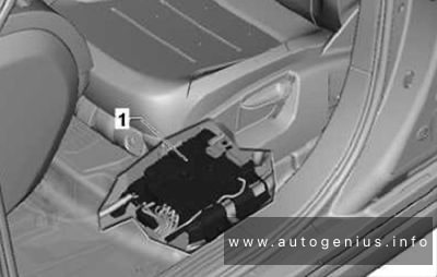
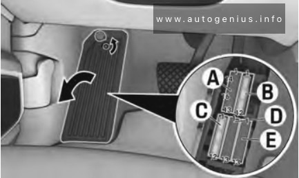
LHD: The fuses are located in the left footwell under the footrest.
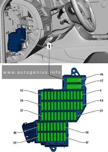
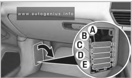
RHD: The fuses are located behind a cover.
Fuse box diagram
Left-hand drive

Right-hand drive
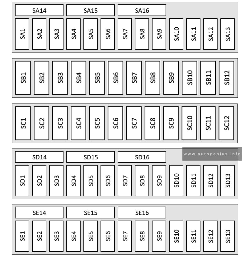
Assignment of the fuses in the passenger compartment (footwell)
| № | Amps | Function / component |
|---|---|---|
| SA1 | – | – |
| SA2 | 10A | Circulation pump, MAF sensor, crankcase heating, coolant circulation pump |
| SA3 | – | Radiator shutter |
| SA4 | 10A | Circulation pump Control unit for NOx sender Control unit for NOx sender 2 Particulate sensor Fuel tank shut-off valve Exhaust flap control unit |
| SA5 | 5A | Brake light switch |
| SA6 | 7.5A/15A | Left electrohydraulic engine mounting solenoid valve Right electrohydraulic engine mounting solenoid valve Inlet cam actuator 1 for cylinder 1~4 Coolant valve for cylinder head Coolant pump Map-controlled engine cooling system thermostat Cam adjustment actuator 1~8 Exhaust gas recirculation cooler changeover valve Exhaust gas recirculation cooling bypass valve 2 Pressure reduction valve Exhaust gas recirculation cooling bypass valve Automatic glow period control unit Glow period control unit 2 Gearbox mounting valve 2 |
| SA7 | 5A/15A | Lambda probe 1 after catalytic converter Lambda probe after particulate filter 2 Air mass measurement module Air mass meter 2 |
| SA8 | 7.5A/15A | Left electrohydraulic engine mounting solenoid valve Coolant valve for gearbox Gearbox mounting valve 1 Secondary air pump relay Control unit for fuel tank leak detection Coolant circulation pump Right electrohydraulic engine mounting solenoid valve Exhaust cam actuator 1 for cylinder 3 Exhaust cam actuator 1 for cylinder 1 Exhaust cam actuator 1 for cylinder 4 Exhaust gas recirculation cooler changeover valve Inlet cam actuator 1 for cylinder 2 Inlet cam actuator 1 for cylinder 3 Inlet cam actuator 1 for cylinder 4 Inlet cam actuator 1 for cylinder 5 Inlet cam actuator 1 for cylinder 6 Continued coolant circulation pump Map-controlled engine cooling system thermostat Fuel pressure regulating valve Fuel metering valve Metering pump 2 |
| SA9 | 5A | Engine component current supply relay (motor relay) |
| SA10 | 5A | Oil level and oil temperature sender |
| SA11 | 7.5A | Accelerator pedal module, Radiator shutter |
| SA12 | 7.5A/10A/15A | Air filter bypass flap valve Secondary air inlet valve Left electrohydraulic engine mounting solenoid valve Right electrohydraulic engine mounting solenoid valve Piston cooling jet control valve Valve for oil pressure control Intake manifold flap valve Turbocharger air recirculation valve Camshaft control valve 1 Exhaust camshaft control valve 1 Activated charcoal filter solenoid valve 1 Exhaust camshaft control valve 2 Camshaft control valve 2 Charge pressure control solenoid valve Inlet cam actuator 1 for cylinder 1~8 Exhaust cam actuator 1 for cylinder 1~8 |
| SA13 | 5A | Radiator fan |
| SA14 | 15A/25A | Engine/motor control unit Injector 2, cylinder 1~4 |
| SA15 | 10A/15A | Lambda probe 1 after catalytic converter Lambda probe 1 before catalytic converter Lambda probe after particulate filter |
| SA16 | 30A | Fuel pump control unit |
| SB1 | 20A | Ignition coil 1~6 with output stage |
| SB2 | – | Motor relay |
| SB3 | – | – |
| SB4 | – | – |
| SB5 | 30A | Electrohydraulic engine mounting control unit |
| SB6 | 25A | Front left seat belt |
| SB7 | 20A/40A | Fuse holder F |
| SB8 | 25A | Front right seat belt |
| SB9 | 20A/30A | Fresh air blower control unit |
| SB10 | – | Driver assistance control |
| SB11 | 40A/15A | Starter relay 2 Thermal management control unit |
| SB12 | – | Allwheel drive |
| SC1 | 30A | Onboard supply control unit, Front seat heating |
| SC2 | 20A | Driver door control unit |
| SC3 | 20A | Onboard supply control unit (Socket supply) |
| SC4 | 30A | Sliding sunroof adjustment control unit |
| SC5 | 30A | Onboard supply control unit, Additional lighting, left |
| SC6 | 20A | Rear driver side door control unit |
| SC7 | 30A | Wiper motor control unit |
| SC8 | 20A | Rear passenger side door control unit |
| SC9 | 30A | Onboard supply control unit, (Additional lighting, right) |
| SC10 | 10A/30A | Onboard supply control unit, Headlight / windshield washer system |
| SC11 | 20A/30A | Potentiometer for electric trailer brakes, Air-conditioning control unit |
| SC12 | 30A | Auxiliary heater control unit Clutch actuator |
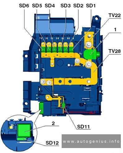
| SD1 | 5A | Interior mirror Heated rear seats control unit Diagnostic connection |
| SD2 | 10A | Data bus diagnostic interface Onboard supply control unit, Parking sensors |
| SD3 | 7.5A | Engine sound generator control unit, Sound system (E-Hybrid), |
| SD4 | 5A | Gearbox oil cooling valve |
| SD5 | 5A | Starter relay 1 Starter relay 2 Power and control electronics for electric drive |
| SD6 | – | – |
| SD7 | 15A | Accelerator pedal module |
| SD8 | 5A | Control unit for night vision system Anti-roll bar control unit Anti-roll bar control unit 2 |
| SD9 | 10A | Adaptive cruise control unit Front left radar sensor control unit for object detection Front right radar sensor control unit for object detection |
| SD10 | – | Allwheel drive, differential lock |
| SD11 | 10A | Front camera for driver assist systems |
| SD12 | 7.5A | Front left seat backrest fan 1 Front left seat cushion fan 1 Front right seat backrest fan 1 Front right seat cushion fan 1 |
| SD13 | 5A | USB charging socket 1 |
| SD14 | 15A | Rear window wiper motor |
| SD15 | 20A | Front right headlight |
| SD16 | 20A | Front left headlight |
| SE1 | 5A | Anti-theft alarm sensor Alarm horn |
| SE2 | 5A | Main relay |
| SE3 | 5A | Garage door operating unit |
| SE4 | 7.5A | Selector lever sensors control unit |
| SE5 | 15A | Onboard supply control unit (Horn) |
| SE6 | 5A | Electromechanical parking brake button |
| SE7 | 5A/10A | Data bus diagnostic interface (Gateway control unit) |
| SE8 | 5A | Front roof module |
| SE9 | – | Emergency call module, trailer hitch |
| SE10 | 5A/10A | Airbag control unit |
| SE11 | 5A | ABS control unit, ESC |
| SE12 | 10A | Rain and light sensor Diagnostic connection |
| SE13 | 20A | Onboard supply control unit (Air conditioning system) |
| SE14 | 20A | Front passenger door control unit |
| SE15 | 20A | Onboard supply control unit, Air-conditioning compressor |
| SE16 | 30A | DC/AC converter with socket, 12V – 230V Brake system pressure accumulator, Smart actuator (E-Hybrid) |
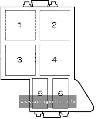
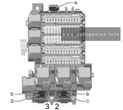
Single fuses (LHD)
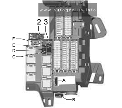
Single fuses (LHD)
| No. |
A |
Function/component |
| A | 15A | Seat and steering column adjustment control unit with memory |
| B | 15A | Front passenger seat adjustment with memory control unit |
| C | 40A | ABS control unit |
| D | 40A | ABS control unit |
| E | – | – |
| F | 50A | Gearbox auxiliary hydraulic pump |
Single fuses (RHD)
Single fuses (RHD)
| № | Amps | Function / component |
|---|---|---|
| A | 15A | Seat and steering column adjustment control unit with memory |
| B | 40A | ABS control unit |
| C | 40A | ABS control unit |
| D | – | – |
| E | – | – |
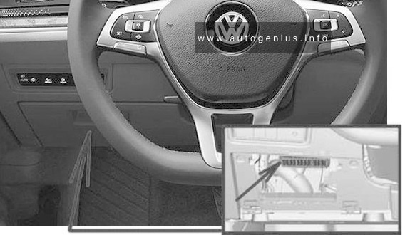
Driver’s Side Instrument Panel Fuse Box
Fuse Box Location
The fuses are located behind a cover on the driver’s side (both LHD and RHD).
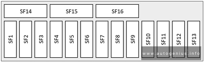
Fuse Box Diagram
Left-hand drive
Right-hand drive
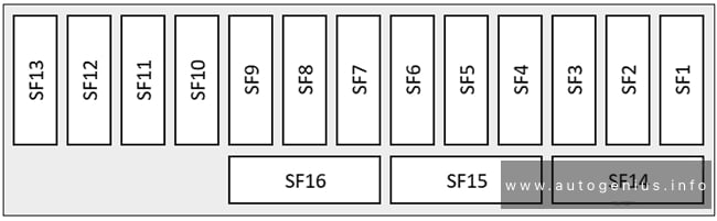
Assignment of the fuses in the instrument panel
| № | Amps | Function / component |
|---|---|---|
| SF1 | – | – |
| SF2 | 5A | Left effect loudspeaker |
| SF3 | 5A/7.5A | Operating unit for driving mode selection Operating unit to regulate suspension height Button for driver assist systems Switch module 1 in centre console |
| SF4 | 5A | Control unit for Head-up Display |
| SF5 | 7.5A | USB hub |
| SF6 | 10A | Heater and air conditioning controls |
| SF7 | 5A/10A | Steering column lock control element |
| SF8 | 5A/10A | Multimedia system operating unit |
| SF9 | 10A | Control unit in dash panel insert |
| SF10 | 5A | Multimedia system operating unit |
| SF11 | 5A | Rotary light switch |
| SF12 | 1A | Steering column electronics control unit |
| SF13 | – | – |
| SF14 | 5A/20A | Control unit 1 for information electronics |
| SF15 | 25A | Control unit for electrically adjustable steering column |
| SF16 | 10A | Steering column electronics control unit |
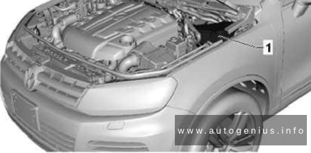
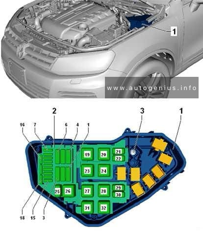
Engine Compartment Fuse Box

| Slot | Amps | Function / component |
|---|---|---|
| A | 15A | Engine/motor control unit |
| B | – | – |
Luggage compartment
Fuse box location
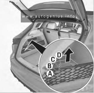
Fuse box diagram
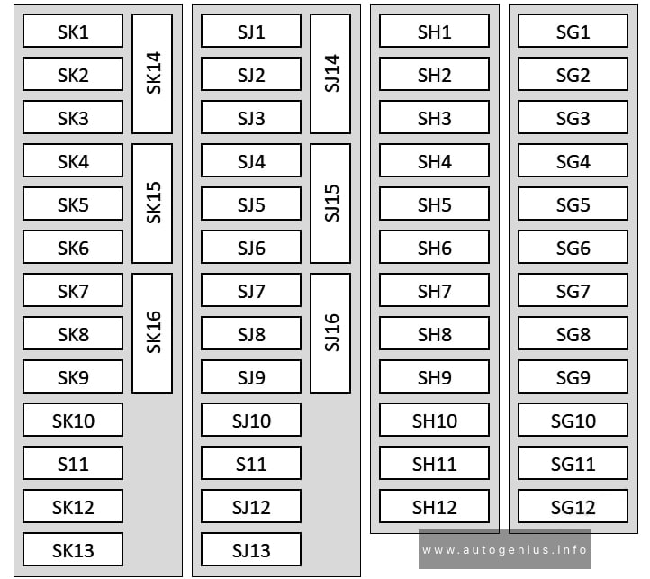
Assignment of the fuses in the luggage compartment
| № | Amps | Function / component |
|---|---|---|
| SG1 | 10A | Refrigerant pressure and temperature sender 1 Refrigerant pressure and temperature sender 2 Refrigerant expansion valve 2 High-voltage heater (PTC) Radiator blind control motor |
| SG2 | – | – |
| SG3 | – | – |
| SG4 | – | – |
| SG5 | 15A | Adaptive suspension control unit |
| SG6 | 15A | Automatic gearbox control unit |
| SG7 | 20A | Onboard supply control unit 2 |
| SG8 | 25A | Operating and display unit for rear air conditioning system |
| SG9 | – | – |
| SG10 | 25A | Trailer detector control unit |
| SG11 | 30A | Rear lid control unit |
| SG12 | 20A | Rear fresh air blower control unit |
| SH1 | 20A | Onboard supply control unit 2 |
| SH2 | – | – |
| SH3 | 30A | Control unit for reducing agent metering system DC/AC converter with socket, 12V – 230V |
| SH4 | 10A | Operating and display unit for rear air conditioning system |
| SH5 | 25A | Trailer detector control unit |
| SH6 | 30A | Trailer detector control unit |
| SH7 | 15A | Trailer detector control unit |
| SH8 | – | – |
| SH9 | 15A | Trailer detector control unit |
| SH10 | – | – |
| SH11 | – | – |
| SH12 | 25A | Control unit for reducing agent metering system |
| SJ1 | 15A | Driver assist systems control unit |
| SJ2 | 5A | Aerial amplifier for mobile telephone |
| SJ3 | – | – |
| SJ4 | 5A | Lane change assist control unit Lane change assist control unit 2 |
| SJ5 | – | – |
| SJ6 | 5A | Tyre Pressure Monitoring System control unit |
| SJ7 | 15A | Driver assist systems control unit |
| SJ8 | 5A | Remote control receiver for auxiliary heater |
| SJ9 | – | – |
| SJ10 | 5A | TV tuner |
| SJ11 | 5A | Roof aerial |
| SJ12 | 5A | Garage door operation control unit |
| SJ13 | 5A | Reversing camera system control unit |
| SJ14 | 20A | Onboard supply control unit 2 |
| SJ15 | – | – |
| SJ16 | 40A | Digital sound package control unit |
| SK1 | 5A | Roll stabiliser control unit Roll stabiliser control unit 2 |
| SK2 | 7.5A | Maintenance connector for high-voltage system |
| SK3 | 10A | High-voltage battery coolant pump relay |
| SK4 | 7.5A | Power and control electronics for electric drive |
| SK5 | 5A | Brake servo |
| SK6 | – | – |
| SK7 | – | – |
| SK8 | 5A | Air conditioner compressor with magnetic coupling and regulating valve |
| SK9 | 10A | Battery, 48 V Voltage converter (48V/12V) |
| SK10 | 5A | High-voltage battery 1 |
| SK11 | 7.5A | Charging unit 1 for high-voltage battery |
| SK12 | – | – |
| SK13 | – | – |
| SK14 | 20A | Thermal management coolant pump relay |
| SK15 | – | – |
| SK16 | – | – |
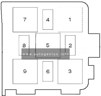
Single fuses
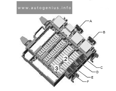
Single fuses (luggage compartment)
| № | Amps | Function / component |
|---|---|---|
| A | 15A | Front passenger seat adjustment with memory control unit (right-hand drive) |
| B | – | – |
| C | 30A | Heated rear window relay |
| D | 40A | Adaptive suspension compressor electronics |
| E | – | – |
| F | – | – |
WARNING: Terminal and harness assignments for individual connectors will vary depending on vehicle equipment level, model, and market.