Toyota Previa (2009 – 2012) – fuse and relay box diagram
Year of production: 2009, 2010, 2011, 2011, 2012
The Toyota Previa is a versatile and spacious minivan, also known as an MPV (multi-purpose vehicle), that has been sold globally under different names. In some markets, like Australia, it was sold as the Toyota Tarago, while in others it retained the Previa name. It is renowned for its futuristic design, reliability, and practical features, making it a popular choice for families and commercial users alike.
Key Features of the Toyota Previa:
1.Unique Design: The Previa had a distinctive egg-shaped design, especially in its earlier generations, which made it stand out among other minivans. The rounded aerodynamic body contributed to better fuel efficiency and reduced drag.
2.Seating Capacity: Depending on the market and configuration, the Previa typically offered seating for 7 to 8 passengers, making it a spacious option for families.
3.Mid-Engine Layout: One of the most unique aspects of the first-generation Previa was its mid-engine design. The engine was located under the front seats, which allowed for better weight distribution but made maintenance slightly more challenging.
4.All-Wheel Drive (AWD): Some versions of the Previa were available with all-wheel drive, enhancing traction and making it suitable for a variety of driving conditions, including rough terrain or snow.
5.Sliding Doors: The Previa featured sliding rear doors for easier passenger entry and exit, especially in tight parking spaces.
6.Flexible Interior: With foldable or removable rear seats, the Previa was designed to offer flexible space for both passengers and cargo.
Generations:
1.First Generation (1990–1999):
•This model had a very unconventional design with a mid-engine layout. The engine was mounted underneath the front seats, and it featured rear-wheel drive or optional all-wheel drive.
•Engine options included a 2.4-liter inline-4 engine and later models offered supercharged variants for more power.
•The Previa was known for its durability and spacious interior, despite its somewhat unconventional engine placement.
2.Second Generation (2000–2006):
•The second-generation Previa featured a more traditional front-engine, front-wheel-drive layout.
•It was available with a range of engines, including more fuel-efficient options. In some markets, it came with a V6 engine.
•The design was more streamlined and modern, with improved safety features and more advanced technology in the interior.
•Toyota focused on comfort and refinement, making it more family-friendly.
3.Third Generation (2006–2019):
•This generation offered even more refinement in terms of luxury, technology, and performance.
•It came with advanced features like dual-zone climate control, premium audio systems, and even hybrid variants in some regions.
•By this generation, the Previa was primarily marketed in Asia, while markets like North America received the Toyota Sienna as the main minivan option.
Previa Hybrid:
In the later years, Toyota introduced a hybrid version of the Previa, particularly in the Asian markets. It featured Toyota’s Hybrid Synergy Drive, combining a gasoline engine with an electric motor to improve fuel efficiency, making it an eco-friendlier option for larger families.
Successors:
In many regions, the Toyota Previa was phased out or replaced by other models, such as the Toyota Alphard, Toyota Estima, or the Toyota Sienna (in North America). Despite this, the Previa remains a memorable model due to its distinctive design and practicality.
The Previa is still favored in the used car market for those looking for a reliable, spacious vehicle with Toyota’s legendary durability.
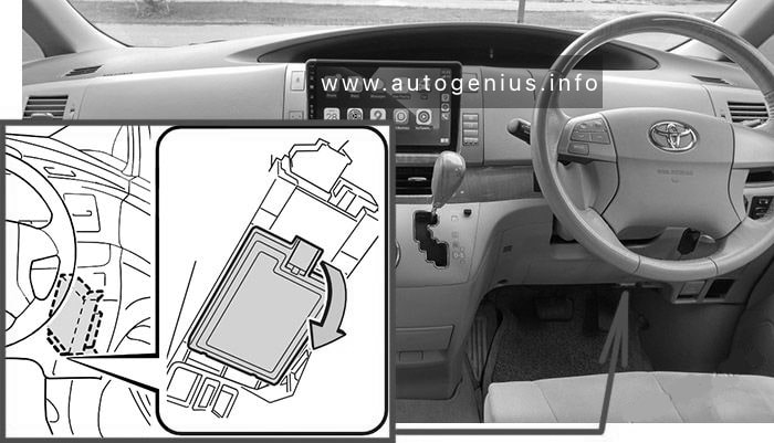
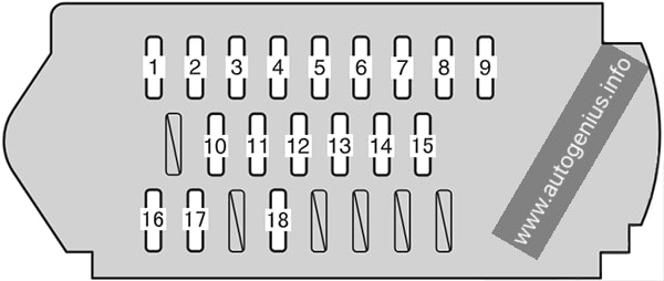
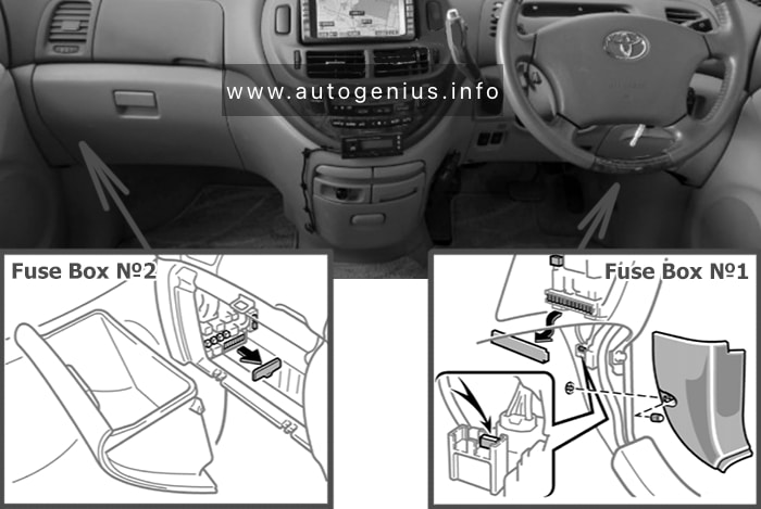
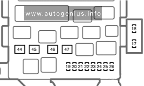
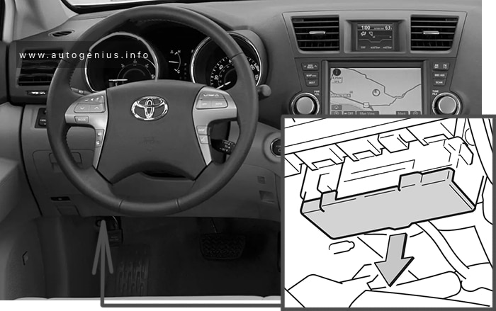
Instrument Panel Fuse Box №1 (left side)
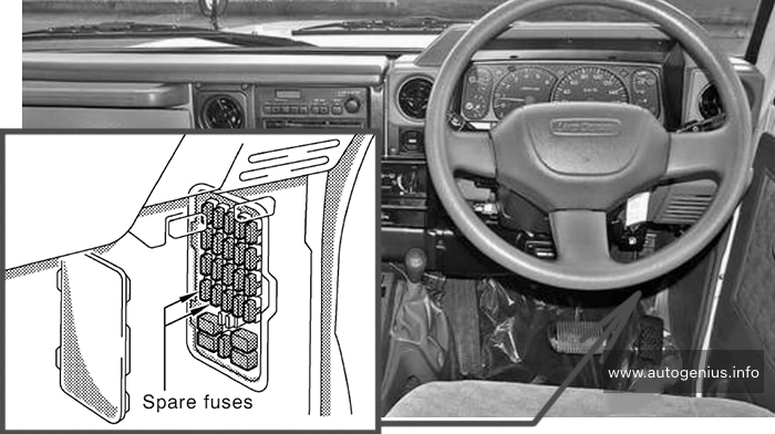
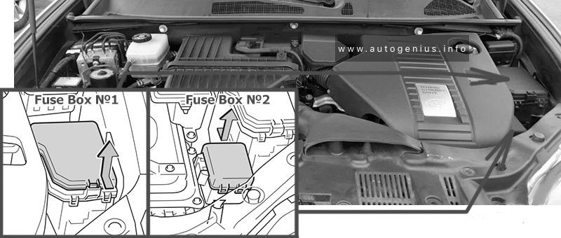
Fuse Box Location
Remove the cover; Remove the lid.

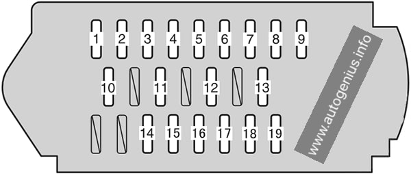
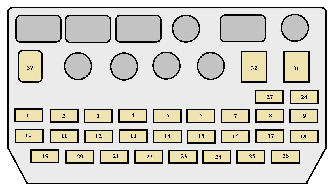
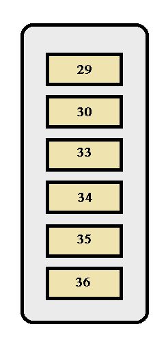
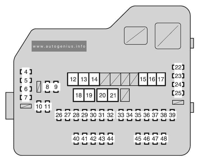
Fuse Box Diagram
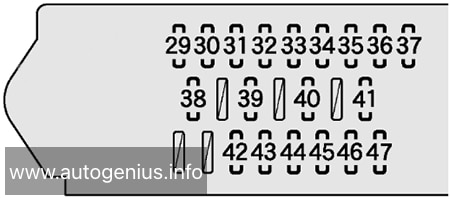
Assignment of the fuses in the Fuse Box №1
| № | Name | Amp | Description |
|---|---|---|---|
| 29 | WELCAB | 30A | No circuit |
| 30 | 4WD | 7.5A | No circuit |
| 31 | AC INV | 15A | No circuit |
| 32 | DR LOCK | 30A | Multiplex communication system |
| 33 | P/W FL | 20A | Power windows |
| 34 | S/R | 20A | Rear sunshade |
| 35 | PSD LH | 30A | Power slide door |
| 36 | P/W RL | 20A | Power windows |
| 37 | PBD | 30A | No circuit |
| 38 | RR WIP | 15A | Windshield wipers and washer, rear window wiper and washer, headlight cleaner |
| 39 | GAUGE №1 | 10A | Anti-lock brake system, vehicle stability control system, adaptive front lighting system, electric cooling fan, Toyota parking assist system, headlight cleaner |
| 40 | PANEL | 10A | Instrument panel lights, Toyota parking assist system |
| 41 | TAIL | 10A | Front fog lights, tail lights, position lights, license plate lights |
| 42 | LH ECU-IG | 10A | Adaptive front lighting system, multiplex communication system, power rear seat, power slide door |
| 43 | SEAT HTR LH | 10A | Seat heater LH |
| 44 | GAUGE №2 | 10A | Charging system, automatic transmission system, backup lights, Toyota parking assist system |
| 45 | STP RR | 7.5A | No circuit |
| 46 | STP HI MT | 7.5A | No circuit |
| 47 | STP RL | 7.5A | No circuit |
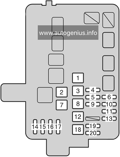
Instrument Panel Fuse Box №2 (right side)
Fuse Box Location
Remove the lid.

Fuse Box Diagram
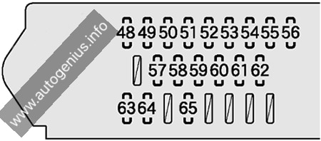
Assignment of the fuses in the Fuse Box №2
| № | Name | Amp | Description |
|---|---|---|---|
| 48 | PSB | 30A | No circuit |
| 49 | RR FOG | 7.5A | No circuit |
| 50 | P/W FR | 20A | Power windows |
| 51 | P/SEAT RH | 30A | Power seat |
| 52 | AM1 | 7.5A | Starting system |
| 53 | STOP | 15A | Stop lights, high mounted stoplight, automatic transmission system, shift lock control system, multiport fuel injection system / sequential multi-port fuel injection system, anti-lock brake system, vehicle stability control system |
| 54 | OBD | 7.5A | On-board diagnosis system |
| 55 | PSD RH | 30A | Power slide door |
| 56 | P/W RR | 20A | Power windows |
| 57 | P/POINT | 15A | Power outlet |
| 58 | CIG | 15A | Cigarette lighter |
| 59 | RAD №2 | 7.5A | Audio system, rear seat entertainment system |
| 60 | ECU-ACC | 7.5A | Power rear view mirrors, shift lock system |
| 61 | IGN | 10A | Multiport fuel injection system / sequential multiport fuel injection system, SRS airbag system, multiplex communication system |
| 62 | MET | 7.5A | Gauges and meters |
| 63 | FR WIP | 30A | Windshield wipers and washer |
| 64 | SEAT HTR RH | 10A | Seat heater RH |
| 65 | RH ECU-IG | 10A | Vehicle stability control system, air conditioning system, Toyota parking assist system, automatic transmission system, electric power steering system, power slide door, rear power sunshade, shift lock system, turn signal flashers, emergency flashers, vanity lights, multiplex communication system |
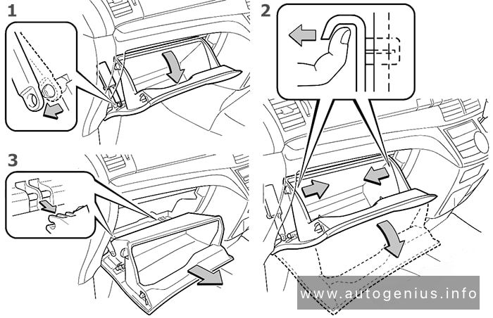
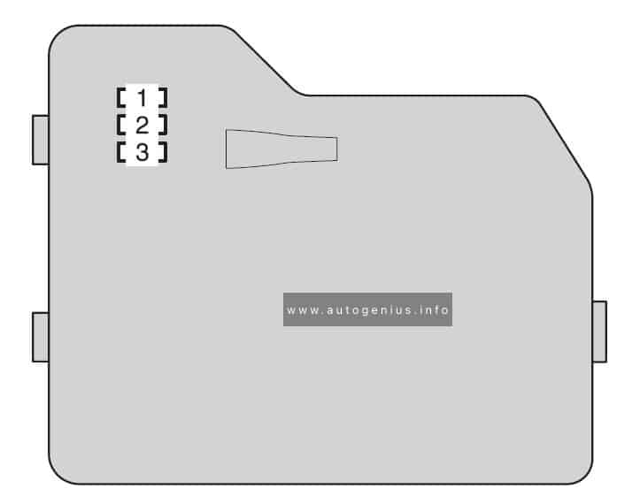
Instrument Panel Fuse Box №3
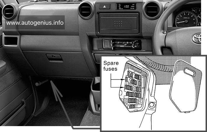
Fuse Box Location
Remove the lid.
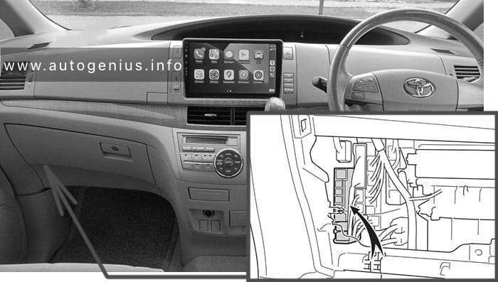
To access:
- Open the glove box. Slide off the damper.
- Pull both side of the glove box from the inside to disconnect the upper claws.
- Pull out the glove box and disconnect the lower claws.

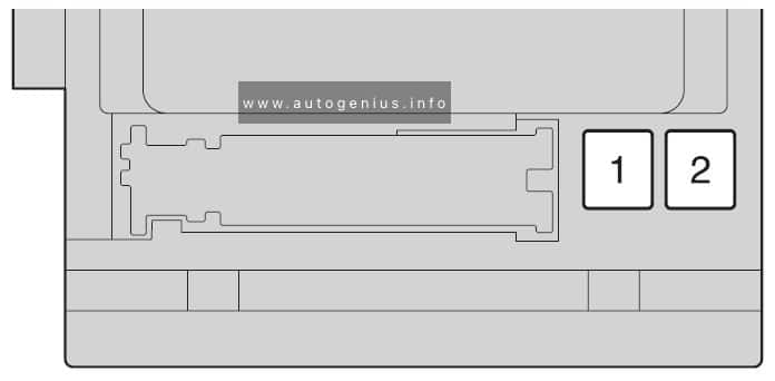
Fuse Box Diagram
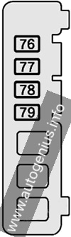
Assignment of the fuses in the Fuse Box №3
| № | Name | Amp | Description |
|---|---|---|---|
| 76 | HTR | 50A | Air conditioning system |
| 77 | 3RD SEAT RH | 30A | Power rear seat |
| 78 | 3RD SEAT LH | 30A | Power rear seat |
| 79 | RR A/C | 30A | Air conditioning system |
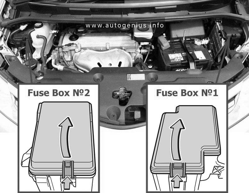
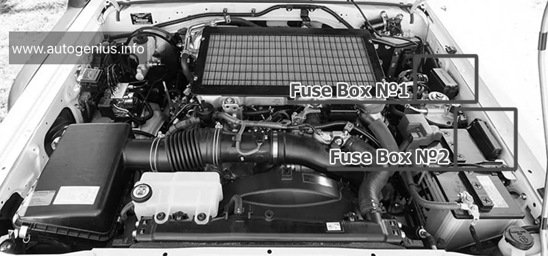
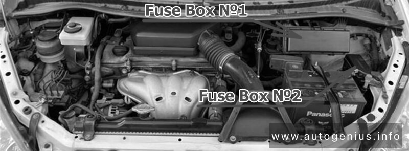
Engine Compartment
Fuse Box Location
Push the tab in and lift the lid off.

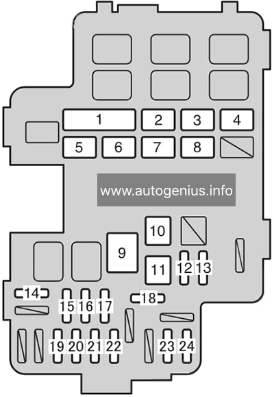
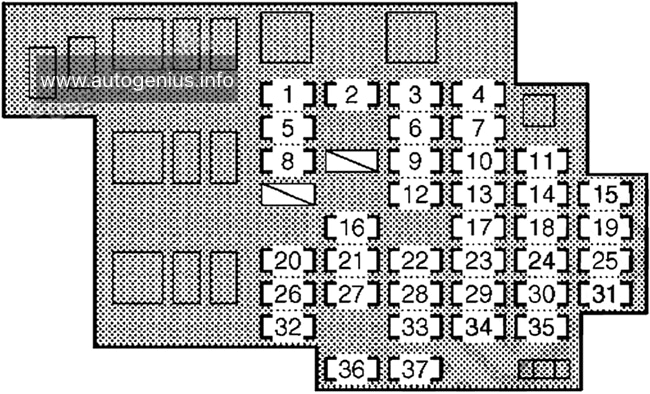
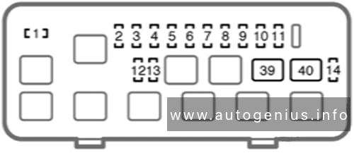
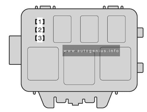
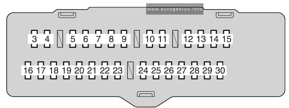
Fuse Box №1 Diagrams
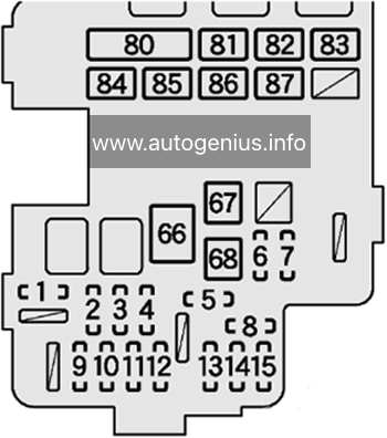
Assignment of the fuses in the Engine Compartment Fuse Box №1
| № | Name | Amp | Description |
|---|---|---|---|
| 1 | EFI | 20A | Multiport fuel injection system / sequential multiport fuel injection system |
| 2 | ECU-B | 10A | Gauges and meters, air conditioning system, power slide door, multiplex communication system, wireless remote control system |
| 3 | DOME | 7.5A | Interior lights, luggage room light, door courtesy lights, front personal lights, multiplex communication system |
| 4 | RAD №1 | 15A | Audio system, rear seat entertainment system |
| 5 | MIR HTR | 10A | Outside rear view mirror |
| 6 | ABS №2 | 30A | Anti-lock brake system, vehicle stability control system |
| 7 | DEF | 25A | Rear window defogger, “MIR HTR” |
| 8 | ST | 5A | No circuit |
| 9 | ETC-S | 10A | Multiport fuel injection system / sequential multiport fuel injection system |
| 10 | AM2 №2 | 7.5A | Multiport fuel injection system / sequential multiport fuel injection system |
| 11 | TRN HAZ | 15A | Turn signal flashers, emergency flashers |
| 12 | IG2 | 15A | Multiport fuel injection system / sequential multiport fuel injection system, starting system, “MET”, “IGN” fuse |
| 13 | AM2 №1 | 30A | Starting system |
| 14 | FR DOOR | 30A | Multiplex communication system |
| 15 | A/F | 30A | Multiport fuel injection system / sequential multiport fuel injection system |
| 66 | EPS | 80A | Electric power steering system |
| 67 | ST | 30A | Multiport fuel injection system / sequential multiport fuel injection system |
| 68 | ABS №1 | 50A | Anti-lock brake system, vehicle stability control system |
| 80 | RH R/B ALT | 100A | “CDS FAN”, “RDI FAN”, “PTC №1”, “PTC №2”, “PTC №3”, “H-LP CLAN”, “FOG” fuse |
| 81 | RH-MAIN-JB | 60A | “STOP”, “AM1”, “STP HI MT”, “STP RR”, “STP RL”, “OBD”, “P/W RR”, “PSB”, “P/W FR”, “RR FOG”, “P/SEAT RH”, “PSD RH”, “CIG”, “ECU-ACC”, “RAD №2”, “P/POINT”, “FR WIP”, “SEAT HTR RH”, “RH ECU-IG” fuse |
| 82 | LH-MAIN-JB | 80A | “TAIL”, “PANEL”, “P/W RL”, “PSD LH”, “S/R”, “4WD”, “PBD”, “P/W FL”, “DR LOCK”, “GAUGE №1”, “RR WIP”, “SEAT HTR LH”, “GAUGE №2”, “LH ECU-IG”, “WASH” fuse |
| 83 | SUB R/B | 80A | “HTR”, “RR A/C”, “3RD SEAT RH”, “3RD SEAT LH” fuse |
| 84 | F/B ALT | 100A | “ABS №1”, “ABS №2”, “DEF” fuse |
| 85 | ALT | 140A | Gauges and meters, charging system, “F/B ALT”, “SUB R/B”, “RH-MAIN-JB”, “LH-MAIN-JB”, “RH R/B ALT” fuse |
| 86 | F/B BATT | 120A | “EPS”, “ST”, “A/F”, “EFI”, “TRN HAZ”, “IG2”, “FR DOOR”, “ETC-S”, “AM2 №2”, “AM2 №1”, “DOME”, “ECU-B”, “RAD №1” fuse |
| 87 | RH R/B BATT | 60A | Headlight cleaner, “H-LP RL”, “H-LP LL”, “S/HORN”. “ECU-B3”, “ECU-B2”, “AMP”, “STRG LCK”, “HORN”, “H-LP RH”, “H-LP LH” fuse |
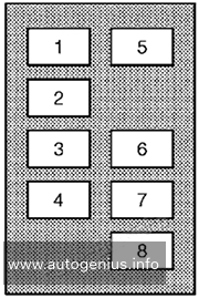
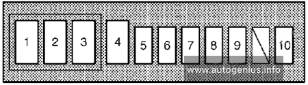
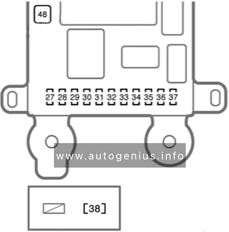
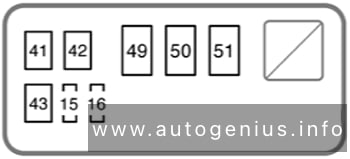
Engine Compartment Fuse Box №2
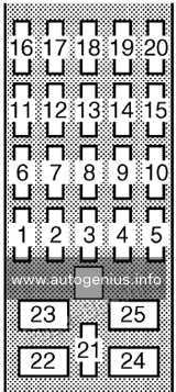
Fuse Box Diagrams
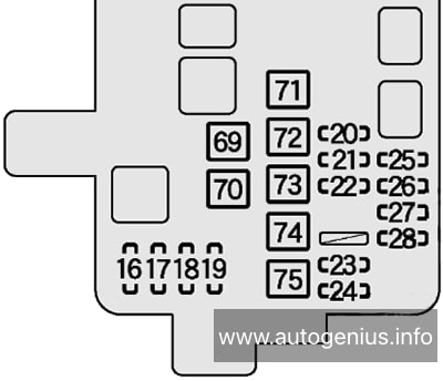
Assignment of the fuses in the Engine Compartment Fuse Box №2
| № | Name | Amp | Description |
|---|---|---|---|
| 16 | H-LP LH | 15A | Left-hand headlight (high beam) |
| 17 | H-LP RH | 15A | Right-hand headlight (high beam) |
| 18 | H-LP LL | 15A | Left-hand headlight (low beam) |
| 19 | H-LP RL | 15A | Headlight beam level control system, right-hand headlight (low beam) |
| 20 | ECU-B3 | 7.5A | No circuit |
| 21 | ECU-B2 | 7.5A | Power windows |
| 22 | S/HORN | 10A | No circuit |
| 23 | DEICER | 20A | No circuit |
| 24 | FOG | 20A | Front fog lights |
| 25 | HORN | 10A | Horns |
| 26 | STRG LCK | 20A | No circuit |
| 27 | AMP2 | 30A | No circuit |
| 28 | AMP1 | 30A | No circuit |
| 69 | CDS FAN / RDI FAN №2 | 50A | Electric cooling fan |
| 70 | RDI FAN / RDI FAN №1 | 50A | Electric cooling fan |
| 71 | WEL CAB | 30A | No circuit |
| 72 | H-LP CLN | 30A | Headlight cleaner |
| 73 | PTC №3 | 50A | Air conditioning system |
| 74 | PTC №2 | 50A | Air conditioning system |
| 75 | PTC №1 | 50A | Air conditioning system |
WARNING: Terminal and harness assignments for individual connectors will vary depending on vehicle equipment level, model, and market.