Volkswagen Transporter (T6; 2016 – 2019) – fuse and relay box diagram
Year of production: 2016, 2017, 2018, 2019
This article focuses on the sixth-generation Volkswagen Transporter (T6), manufactured from 2015 to 2019. It includes fuse box diagrams for Volkswagen Transporter T6 models from 2016 to 2019, provides details on the location of the fuse panels within the vehicle, and explains the function and layout of each fuse and relay.
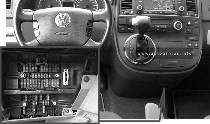
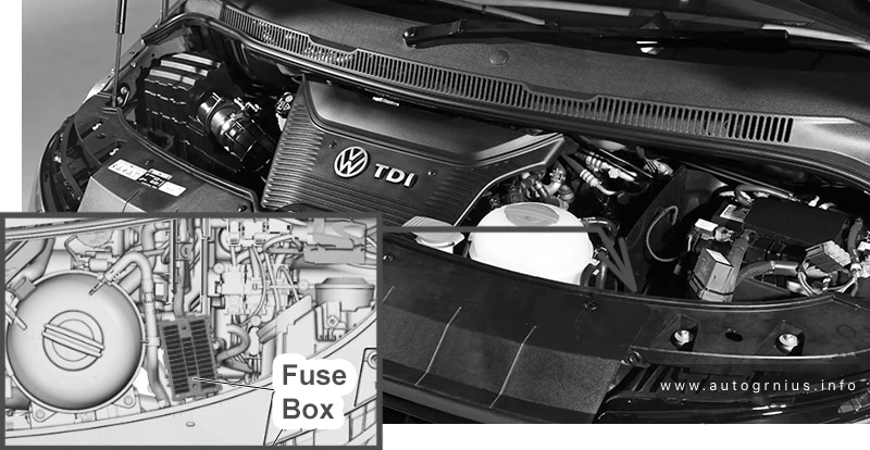
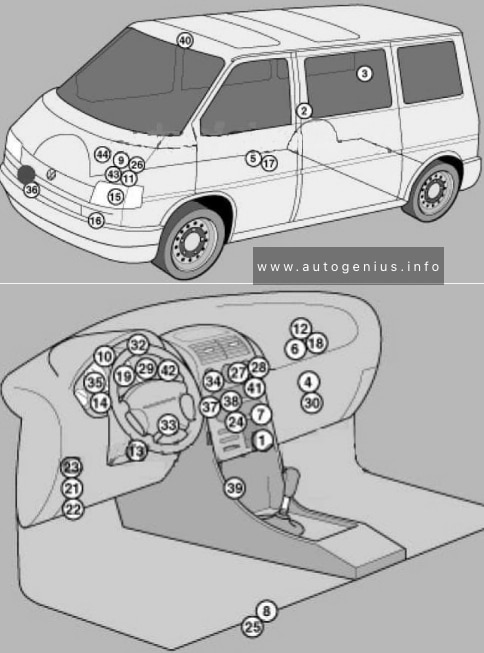
Fuse Box Location
| № | Component |
|---|---|
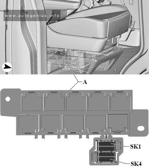
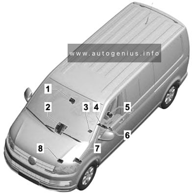
| 1 | Fuse holder K -SK- |
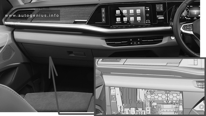
| 2 | Fuse holder C -SC-, Fuse holder D -SD- and Fuse holder F -SF-, in centre of dash panel |
| 3 | Hot air blower single fuse -S25- and Window regulator thermal fuse |
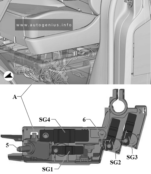
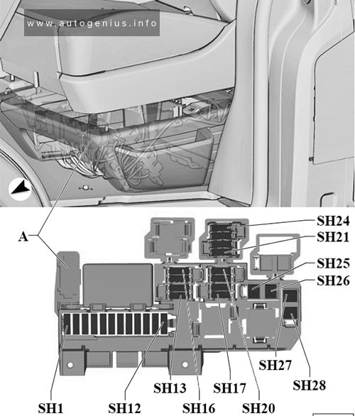
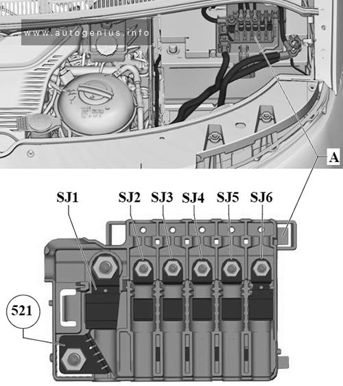
| 4 | Fuse 1 -S131-, fuse 2 -S132-, fuse 3 -S133-, fuse holder H -SH- (-SH1- to -SH30-) and fuse holder J -SJ-, under the left seat box |
| 5 | Fuse holder H -SH- (-SH35- to -SH50-), under the seat-box on the left |
| 6 | Fuse 31 in fuse holder H -SH31-, under the seat-box on the left |
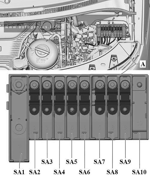
| 7 | Fuse holder A -SA-, on left in engine compartment |
| 8 | Fuse holder B -SB-, on left in engine compartment |
Fuse Holder K -SK-
Assignment of the fuses in the Fuse Holder K – SK-
| № | Amps | Function/component |
|---|---|---|
| 1 | – | not assigned |
| 2/1 | – | not assigned |
| 2/2 | 3 A | Multimedia system display unit 1 (only models with Rear Seat Entertainment) |
| 2/3 | 3 A | Multimedia system display unit 1 (only models with Rear Seat Entertainment) |
| 3-8 | – | not assigned |
Single fuse -S25- and thermal fuse -S43-
| № | Amps | Function/component |
|---|---|---|
| 1 | 40 A | Hot air blower single fuse -S25-: Fresh air blower switch Air conditioning system control unit |
| 2 | 30 A | Window regulator thermal fuse -S43-: Driver door control unit Front passenger door control unit |
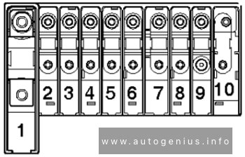
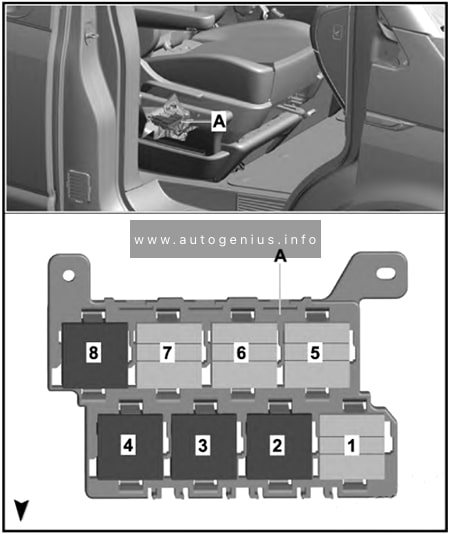
Fuse Holder A -SA-
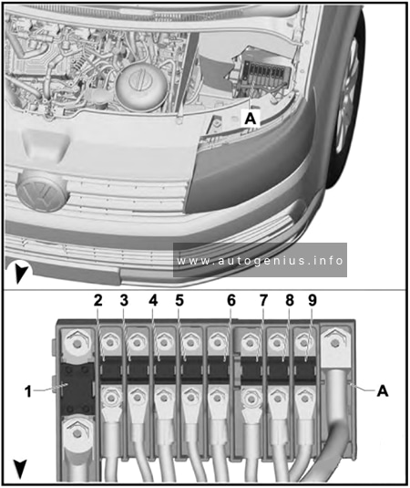
Assignment of the fuses in the Fuse Holder A -SA-
| № | Amps | Function/component |
|---|---|---|
| 1 | 225 A | Alternator |
| 2 | 125 A | Fuse holder C -SC- (-SC1- to -SC17-) |
| 3 | 50 A / 100 A | Battery isolation relay Second battery charging circuit relay Fuses in fuse holder H: #25, 27 Left sliding door control unit Right sliding door control unit |
| 4 | 70 A | Positive connection (30) in engine compartment wiring harness |
| 5 | 60 A / 80 A | ABS control unit |
| 6 | 100 A | Heated windscreen relay Automatic glow period control unit |
| 7 | 100 A | Radiator fan control unit |
| 8 | 50 A / 100 A | Positive connection 1 (30) in interior wiring harness Positive connection 2 (30) in interior wiring harness Positive connection 3 (30), in main wiring harness |
| 9 | 100 A | Fuse holder C -SC- (-SC38- to -SC54-) |
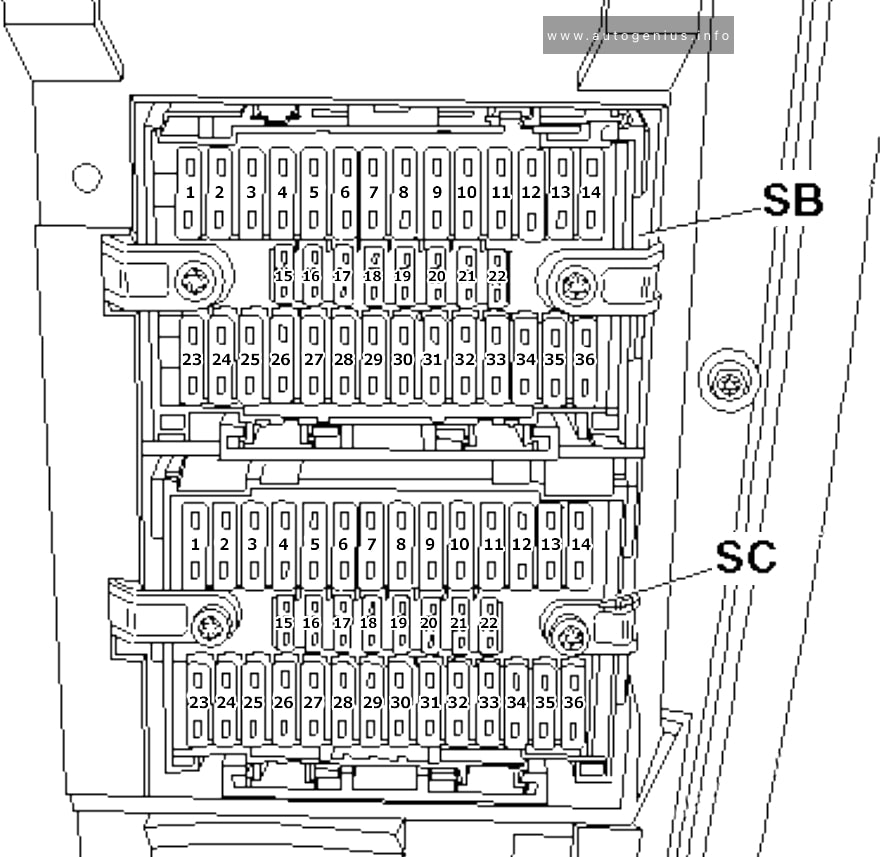
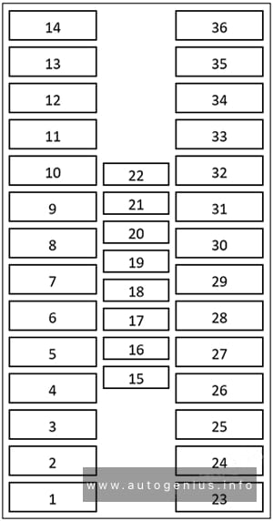
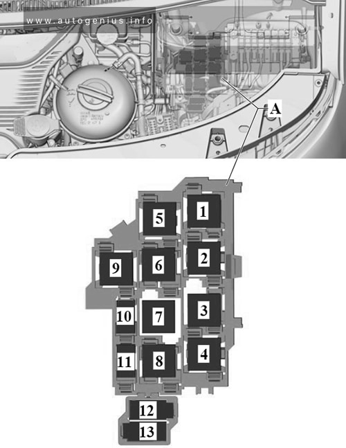
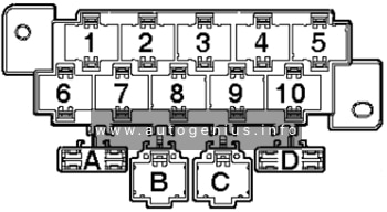
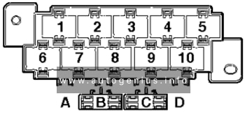
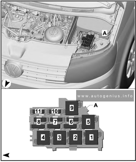
Fuse holder B -SB-
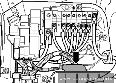
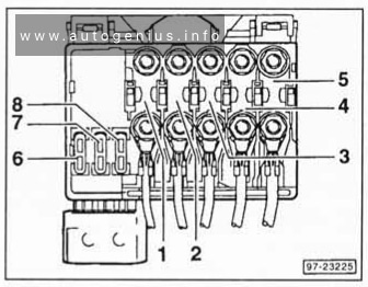
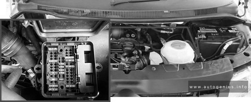
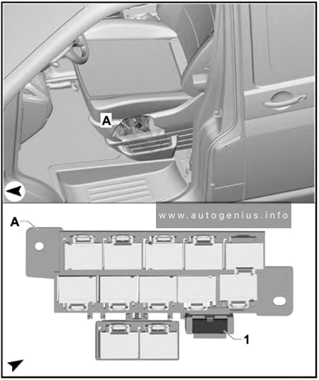
Fuse Box Location
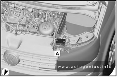

- Open the bonnet;
- If necessary, remove the battery cover. Turn the quick release catches 90 degrees;
- Lift out the partition (1);
- Turn both quick release catches 90 degrees;
- Hold the fuse cover (3) at the front, and fold it upwards.
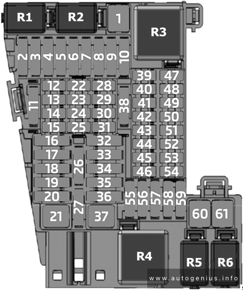
Fuse Box Diagram
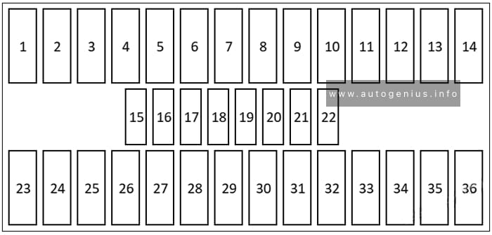
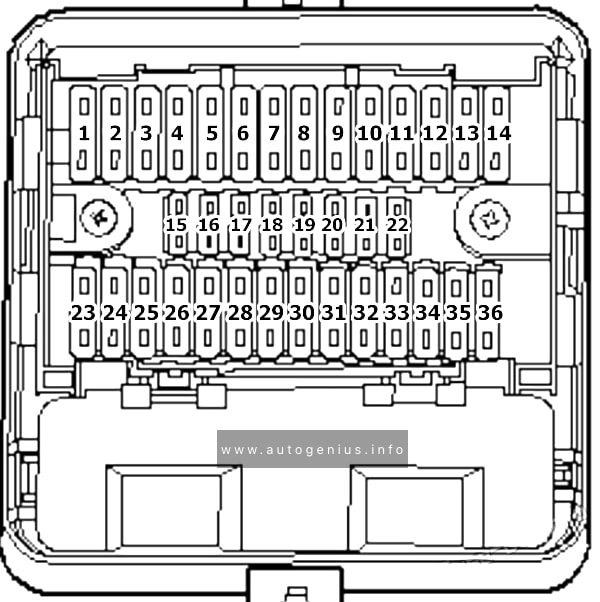
Assignment of the fuses in the Fuse Holder B
| № | Amps | Function/component |
|---|---|---|
| 1 | 5 A | Radiator fan control unit |
| 2 | 5 A | Additional coolant pump relay Residual heat relay Circulation pump |
| 3 | 5 A | Heater element for crankcase breather (petrol, diesel Euro 5) |
| 4 | 30 A | Voltage stabiliser Control unit 1 for information electronics Radio Fuses on fuse holder C: #22, 58 |
| 5 | 15 A | Selector lever Mechatronic unit for dual clutch gearbox Ignition key withdrawal lock solenoid |
| 6 | 30 A | ABS control unit |
| 7 | 5 A | Heater element for crankcase breather (diesel Euro 6) |
| 8 | 30 A | Heated windscreen |
| 9 | 5 A | Engine/motor control unit |
| 10 | 10 A | Charge pressure control solenoid valve (petrol) Activated charcoal filter solenoid valve 1 (petrol) Camshaft control valve 1 (petrol) Turbocharger air recirculation valve (petrol) Intake manifold flap valve (petrol) |
| 10 | 15 A | Charge pressure control solenoid valve (diesel) Exhaust flap valve (diesel Euro 5) Charge pressure control solenoid valve 2 (diesel Euro 6) Intake manifold flap valve (diesel Euro 6) Exhaust gas recirculation cooler changeover valve (diesel Euro 5) Turbine changeover valve (diesel Euro 6) |
| 11 | – | not assigned |
| 12 | 10 A | Fuel pressure regulating valve (diesel Euro 5) Fuel metering valve (diesel) |
| 13 | 7.5 A | Relay for reducing agent metering system (diesel Euro 6) Reducing agent tank (diesel Euro 6) Delivery unit for reducing agent metering system (diesel Euro 6) |
| 14 | 5 A | Fuel pump relay (diesel) Electric fuel pump 2 relay (diesel Euro 5) |
| 15 | 10 A | Reversing light switch |
| 16 | 5 A | Brake light switch |
| 17 | 5 A | TCS and ESP button Tyre Pressure Loss Indicator button Hill descent control button ABS control unit |
| 18 | 5 A | Power steering control unit |
| 19 | 5 A | Clutch pedal switch Clutch position sender Air mass meter (diesel) |
| 20 | 5 A | Engine/motor control unit Air mass meter (petrol) |
| 21 | – | not assigned |
| 22 | – | not assigned |
| 23 | 10 A | Relay for reducing agent metering system |
| 24 | 5 A | Selector lever Mechatronic unit for dual clutch gearbox |
| 25 | 20 A | Actuators 1-8 for camshaft adjustment |
| 26 | 30 A | Heated windscreen |
| 27 | 10 A | Continued coolant circulation pump (diesel Euro 5) Charge air cooling pump (diesel Euro 6) Pump for exhaust gas recirculation cooler (diesel Euro 6) |
| 28 | 15 A | Control unit for sensor electronics (diesel Euro 6) Particulate sensor (diesel Euro 6) Control unit for NOx sender (diesel Euro 6) NOx sender (diesel Euro 6) |
| 29 | 15 A | Valve for oil pressure control (diesel Euro 6) Coolant valve for cylinder head (diesel Euro 6) Auxiliary pump for heating (diesel Euro 6) Fuel shut-off valve switch-off relay (petrol) Fuel pressure regulating valve (petrol) |
| 30 | 20 A | Fuel pump relay (diesel) Fuel system pressurisation pump (diesel) Electric fuel pump 2 relay (diesel Euro 5) Supplementary fuel pump (diesel Euro 5) Fuel pump control unit (petrol) Fuel system pressurisation pump (petrol) |
| 31 | 15 A | Lambda probe Lambda probe heater Lambda probe after catalytic converter (petrol) Lambda probe 1 heater after catalytic converter (petrol) |
| 32 | 30 A | Engine/motor control unit Ignition coils 1-4 with output stage (petrol) |
| 33 | 5 A | Automatic glow period control unit (diesel) Additional coolant pump relay (petrol, diesel Euro 5) Fuel shut-off valve switch-off relay (petrol) Coolant pump relay (petrol) Continued coolant circulation pump (petrol) |
| 34 | 5 A | Onboard supply control unit |
| 35 | 5 A | Battery monitor control unit |
| 36 | 30 A | Starter inhibitor relay Starter |
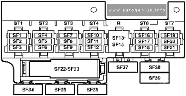
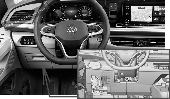
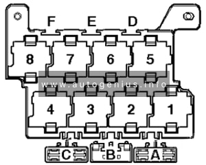
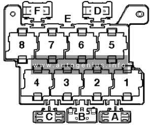
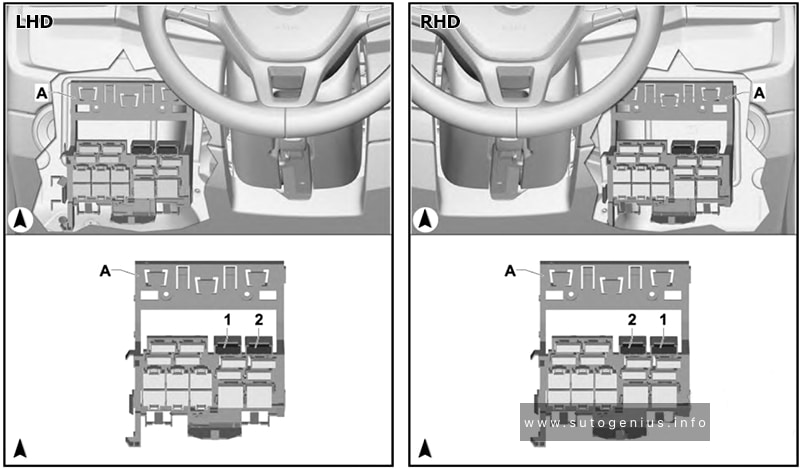
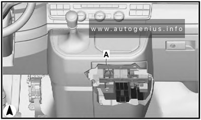
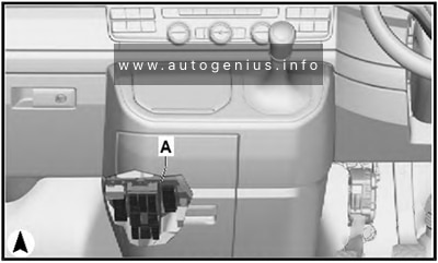
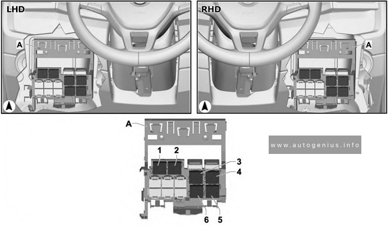
Fuse holders C -SC-, D -SD- and F -SF-
Fuse Box Location
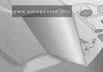
- Grasp into the recess (arrow), and carefully open the cover;
- Carefully pull the cover out of the mountings, and remove it.
Left-hand drive
Right-hand drive
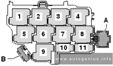
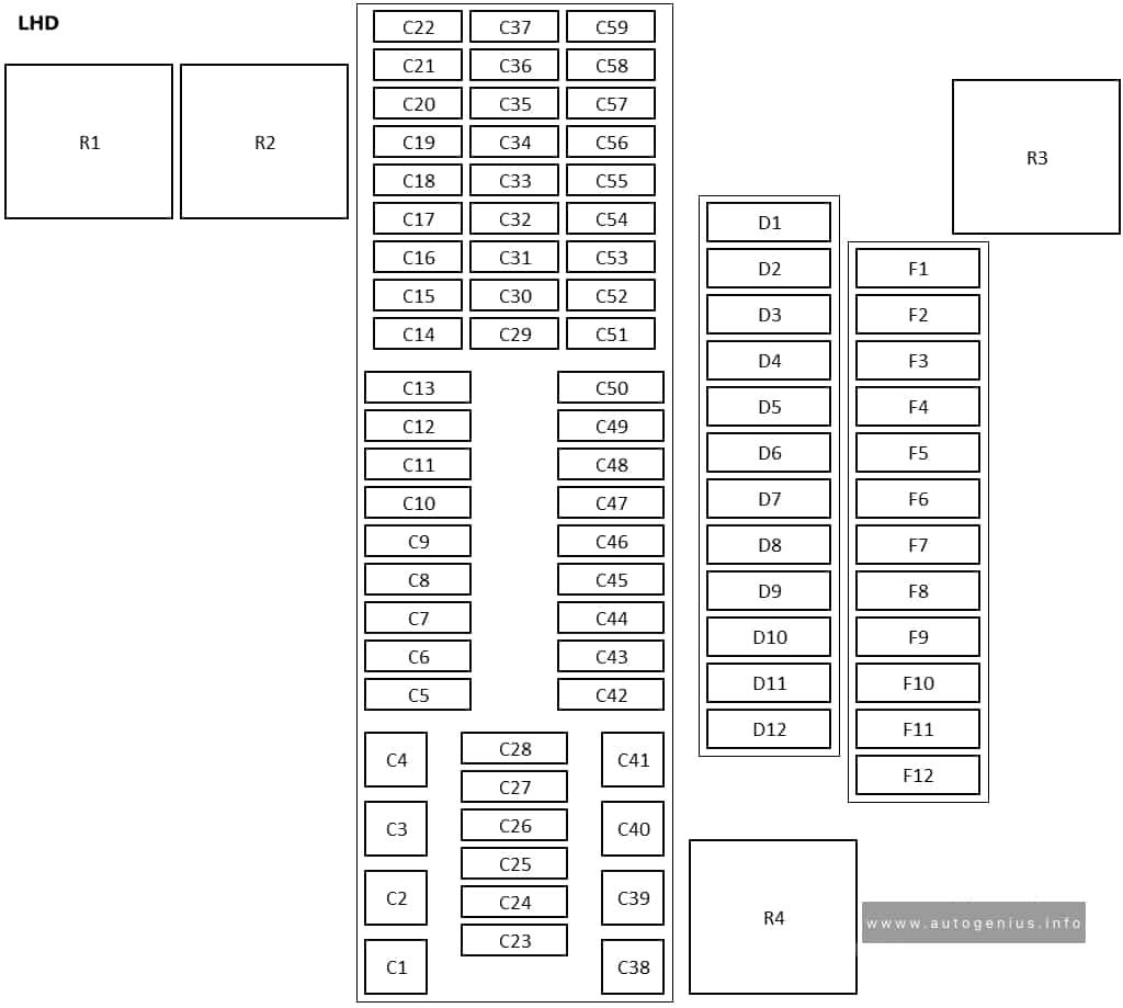
Fuse Box Diagram
Left-hand drive
Right-hand drive
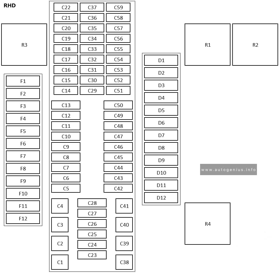
Assignment of the fuses and relays in the instrument panel fuse box (Fuse holders C, D and F)
| № | Amps | Function/component |
|---|---|---|
| C1 | 40 A | Sender for front Bitron blower regulation Fresh air blower Auxiliary coolant heater relay Fresh air blower switch Air conditioning system control unit |
| C2 | 60 A | X-contact relief relay Positive connection (X), in interior wiring harness |
| C3 | 30 A | Onboard supply control unit |
| C4 | 40 A | Window regulator thermal fuse -S43- Fuses on fuse holder C: #18, 22, 57, 58, 59 Fuses on fuse holder D: #1-7, 9 Fuses in fuse holder F: 1, 2, 3, 5, 6, 7, 9, 10 |
| C5 | 7.5 A / 15 A | Onboard supply control unit |
| C6 | 30 A | Onboard supply control unit |
| C7 | 30 A | Terminal 15 voltage supply relay Positive connection 2 (15) in interior wiring harness |
| C8 | 5 A | Light switch |
| C9 | 5 A | Steering column combination switch Headlight dipper and flasher switch Onboard supply control unit |
| C10 | 30 A | Control unit 1 for information electronics Radio |
| C11 | 30 A | Onboard supply control unit |
| C12 | 15 A | Onboard supply control unit |
| C13 | 30 A | Onboard supply control unit |
| C14 | 5 A | Differential lock control unit Isolation relay for powertrain CAN bus 16-pin connector (diagnostics) |
| C15 | 7.5 A | Fresh air and air recirculation flap switch Climatronic control unit Air conditioning system control unit |
| C16 | 5 A | Onboard supply control unit |
| C17 | 10 A | Onboard supply control unit |
| C18 | 7.5 A | USB hub Two-way signal amplifier for mobile telephone/data services Storage compartment with interface for mobile telephone Reversing camera |
| C19 | 7.5 A | Positive connection, in roof wiring harness |
| C20 | 7.5 A | Positive connection 1 (30a) in main wiring harness |
| C21 | 10 A | Onboard supply control unit Relay 1 for ignition bypass Interface for external use 6-pin connector X-contact relief relay |
| C22 | 5 A | Dash panel insert |
| C23 | 5 A | Interface for external use 10-pin connector Starter inhibitor relay |
| C23 | 30 A | Starter Starter inhibitor relay Starter relay 1 Starter relay 2 |
| C24 | 7.5 A | Fresh air and air recirculation flap switch Rear fresh air blower switch Fresh air blower isolation relay |
| C25 | 10 A | Rear window wiper motor Rear left wing door window wiper motor Rear right wing door window wiper motor Left washer jet heater element Right washer jet heater element |
| C26 | 5 A | Terminal 75 voltage supply relay 1 Onboard supply control unit Interface for external use 6-pin connector |
| C26 | 15 A | Interface for external use 10-pin connector |
| C27 | 25 A | Heated front seats control unit |
| C28 | 5 A | Auxiliary coolant heater relay |
| C29 | 10 A | Airbag control unit Warning lamp for airbag deactivated on front passenger side |
| C30 | 10 A | Mirror adjustment switch Headlight range control regulator Accident data recorder button High-pressure sender Air quality sensor Oil level and oil temperature sender Trailer detector control unit Parking aid control unit Headlight range control unit Accident data memory Front left headlight Front right headlight 4-pin connector 10-pin connector Diagnostic connection Left headlight range control motor Right headlight range control motor Coolant shut-off valve relay Climatronic coolant shut-off valve Voltage supply relay 2 Parking aid control unit |
| C31 | – | not assigned |
| C32 | 7.5 A | Light switch Operating and display unit for camping equipment Accident data recorder button Start/Stop operation button Tachograph Steering angle sender Electronically controlled damping control unit Multifunction steering wheel control unit Onboard supply control unit Accident data memory Main beam assist control unit Dash panel insert Automatic anti-dazzle interior mirror Headlight dipper and flasher switch Onboard supply control unit |
| C33 | 10 A | Rear differential lock switch Vacuum switch for rear differential lock All-wheel drive control unit Differential lock control unit Differential lock valve 1 Differential lock valve 2 |
| C34 | 5 A | Operating and display unit for camping equipment Internet access control unit 10-pin connector Interface for external use 10-pin connector |
| C35 | 10 A | 10-pin connector 12-pin connector |
| C35 | 15 A | Taximeter Mirror taximeter Taxi alarm remote control, control unit |
| C36 | 15 A | Intermittent wiper switch Rear wiper switch Washer pump switch (automatic wash/wipe and headlight washer system) Onboard supply control unit Washer pump Rear window wiper motor Windscreen and rear window washer pump Rear left wing door window wiper motor Rear right wing door window wiper motor |
| C37 | 5 A | Cruise control system switch Cruise control system (CCS) SET button Adaptive cruise control unit Lane change assist control unit Lane change assist control unit 2 |
| C38 | 40 A | Ignition/starter switch |
| C39 | 20 A | Ignition/starter switch |
| C40 | 20 A | 12 V socket 6 |
| C40 | 30 A | Auxiliary heater relay Fresh air blower series resistor with overheating fuse |
| C41 | 30 A | Onboard supply control unit |
| C42 | 25 A / 30 A | Fresh air blower isolation relay Rear fresh air blower switch |
| C42 | 30 A | Rear blower regulation sender Rear fresh air blower |
| C43 | 30 A | Control unit for reducing agent heater |
| C44 | 15 A | Rear lid control unit |
| C44 | 20 A | Alarm horn Onboard supply control unit Rear lid control unit Left sliding door control unit Right sliding door control unit |
| C45 | 30 A | Amplifier |
| C46 | 20 A | Auxiliary heater control unit |
| C47 | 25 A | Onboard supply control unit |
| C48 | 25 A | Sliding sunroof adjustment control unit |
| C49 | 15 A | Cigarette lighter |
| C50 | 25 A | Headlight washer system relay Headlight washer system pump |
| C51 | 5 A | Steering angle sender |
| C52 | 5 A | Interior monitor send and receive module 1 Interior monitor send and receive module 2 |
| C53 | 5 A | Rain and light sensor |
| C54 | 7.5 A | Operating and display unit for camping equipment Roof display unit Remote control receiver for auxiliary heater Remote control receiver for auxiliary coolant heater Residual heat relay Circulation pump |
| C55 | 5 A | Operating and display unit for camping equipment Onboard supply control unit Roof hydraulics control unit 10-pin connector Interface for external use 10-pin connector |
| C56 | 5 A | Starter inhibitor relay Engine/motor control unit Interfacefor external use 10-pin connector Interface for external use 10-pin connector |
| C57 | 5 A | Operating and display unit for rear air conditioning system |
| C58 | 10 A | Tachograph |
| C59 | 5 A | Taximeter Mirror taximeter |
| C59 | 10 A | Red cross light switch Red cross light bulb |
| C59 | 10 A | Rotating light switch Rotating light relay Rotating light motor |
| D1 | 5 A | Two-way radio button Front interior light (door contact) button Ignition bypass button Button for daytime running light switch-off |
| D1 | 5 A | Voltage supply relay 1 Voltage supply relay 2 Parking aid control unit |
| D1 | 15 A | Interior light switch (taxi) Taximeter Taxi alarm remote control, control unit Two-way radio |
| D1 | 20 A | All-wheel drive control unit |
| D2 | 30 A | Special vehicle control unit |
| D3 | 15 A | Onboard charging unit Internet access control unit |
| D3 | 15 A | Alarm horn relay Treble horn |
| D3 | 30 A | Rear lid power opening control unit |
| D4 | 10 A | Interior light relay Switch and instrument illumination regulator |
| D4 | 15 A | Alarm system relay 1 Onboard supply control unit Front left headlight |
| D5 | 15 A | Alarm system relay 1 Onboard supply control unit Front right headlight |
| D5 | 15 A | Electronically controlled damping control unit |
| D6 | 15 A | Interface for external use 10-pin connector |
| D6 | 25 A | 10-pin connector |
| D7 | 5 A | Interface for external use 10-pin connector |
| D7 | 5 A | 6-pin connector |
| D7 | 5 A | Interior light switch (taxi) Taxi sign switch |
| D8 | 5 A | Accident data memory |
| D8 | 5 A | Accident data memory 6-pin connector |
| D8 | 15 A | Interface for external use 10-pin connector |
| D9 | 10 A | Relay 1 for ignition bypass Relay 2 for ignition bypass |
| D9 | 25 A | Interface for external use 6-pin connector |
| D10 | 5 A | Interface for external use 10-pin connector 10-pin connector |
| D11 | 10 A | Accident data memory |
| D11 | 15 A | Accident data memory 10-pin connector |
| D11 | 15 A | Interface for external use 10-pin connector |
| D11 | 15 A | Accident data memory Interface for external use 10-pin connector |
| D12 | 3 A | 10-pin connector Interface for external use 10-pin connector |
| F1 | 20 A | All-wheel drive control unit |
| F2 | 5 A / 10 A | Interior light relay Switch and instrument illumination regulator |
| F3 | 30 A | Driver seat adjustment control unit Switch module for front passenger seat Front passenger seat longitudinal adjustment motor Front passenger seat front height adjustment motor Front passenger seat rear height adjustment motor Front passenger seat backrest adjustment motor |
| F4 | 5 A | Emergency call module control unit and communication unit |
| F5 | 15 A | Electronically controlled damping control unit |
| F6 | 30 A | Driver seat adjustment control unit Switch module for front passenger seat Front passenger seat longitudinal adjustment motor Front passenger seat front height adjustment motor Front passenger seat rear height adjustment motor Front passenger seat backrest adjustment motor |
| F7 | 5 A | Accident data memory |
| F8 | – | not assigned |
| F9 | 5 A | Diagnosis wire relay |
| F9 | 5 A | Voltage supply relay 1 Voltage supply relay 2 Parking aid control unit |
| F10 | 30 A | Rear lid power opening control unit |
| F11 | 20 A | 12 V socket 6 |
| F12 | – | not assigned |
| R1 | X-contact relief relay | |
| R2 | Diagnosis wire relay | |
| R2a | Voltage supply relay 1 | |
| R2b | Voltage supply relay 2 | |
| R3 | Fresh air blower isolation relay | |
| R4 | Terminal 15 voltage supply relay |
Fuse Holder H -SH-
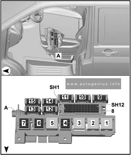
Assignment of the fuses in the Fuse Holder H
| № | Amps | Function/component | |
|---|---|---|---|
| 1-7* | Fuse 1 -S131- | 10 A | Right interior light Rear right interior light Kitchenette light 1 Kitchenette light 3 |
| 1-7* | Fuse 2 -S132- | 15 A | 12 V socket |
| 1-7* | Fuse 3 -S133- | 15 A | 12 V socket 5 Kitchenette light 2 Front left reading light |
| 4.1 | Fuse 13 in fuse holder H -SH13- | 7.5 A | Climatronic control unit |
| 4.1 | Fuse 13 in fuse holder H -SH13- | 30 A | Auxiliary heater relay Fresh air blower series resistor with overheating fuse |
| 4.1 | Fuse 13 in fuse holder H -SH13- | 30 A | Auxiliary heater relay Fresh air blower series resistor with overheating fuse |
| 4.2 | Fuse 14 in fuse holder H -SH14- | – | not assigned |
| 4.3 | Fuse 15 in fuse holder H -SH15- | 30 A | Trailer voltage supply relay Trailer socket |
| 5.1 | Fuse 22 in fuse holder H -SH22- | – | not assigned |
| 5.2 | Fuse 23 in fuse holder H -SH23- | – | not assigned |
| 5.3 | Fuse 24 in fuse holder H -SH24- | – | not assigned |
| 6.1 | Fuse 16 in fuse holder H -SH16- | 30 A | Onboard charging unit Light control relay Kitchenette light 4 |
| 6.2 | Fuse 17 in fuse holder H -SH17- | 30 A | Roof hydraulics control unit |
| 6.3 | Fuse 18 in fuse holder H -SH18- | 10 A | Rear right reading light Right interior light Rear right interior light Kitchenette light 1 Kitchenette light 2 Kitchenette light 3 |
| 7.1 | Fuse 19 in fuse holder H -SH19- | 10 A | Refrigerator box |
| 7.2 | Fuse 20 in fuse holder H -SH20- | 5 A | Water pump switch for shower Water pump switch Coolant pump |
| 7.3 | Fuse 21 in fuse holder H -SH21- | 5 A | Operating and display unit for camping equipment |
| 8.1 | Fuse 1 in fuse holder H -SH1- | 15 A | 12 V socket 2 |
| 8.2 | Fuse 2 in fuse holder H -SH2- | 15 A | Onboard charging unit Map reading light bulb 12 V socket 12 V socket 3 |
| 8.3 | Fuse 3 in fuse holder H -SH3- | 10 A | Switch-over relay 1 for roof ventilator Switch for roof ventilator to ventilate load area Switch for roof ventilator to extract air from load area |
| 8.3 | Fuse 3 in fuse holder H -SH3- | 15 A | 12 V socket 4 |
| 8.4 | Fuse 4 in fuse holder H -SH4- | 15 A | Trailer detector control unit |
| 8.5 | Fuse 5 in fuse holder H -SH5- | 20 A | Trailer detector control unit |
| 8.6 | Fuse 6 in fuse holder H -SH6- | 20 A | Trailer detector control unit |
| 8.7 | Fuse 7 in fuse holder H -SH7- | 15 A | End position button for cupboard light Cupboard light Reading light relay Left luggage compartment light Rear lid light Interior light Front left reading light Front right reading light Rear lid light 2 Kitchen background lighting |
| 8.7 | Fuse 7 in fuse holder H -SH7- | 10 A | 10-pin connector |
| 8.8 | Fuse 8 in fuse holder H -SH8- | – | not assigned |
| 8.9 | Fuse 9 in fuse holder H -SH9- | 5 A | Electric torch |
| 8.10 | Fuse 10 in fuse holder H -SH10- | 15 A | 12 V socket |
| 8.10 | Fuse 10 in fuse holder H -SH10- | 30 A | DC/AC converter with socket, 12 V – 230 V DC/AC converter with socket, 12 V -115 V |
| 8.11 | Fuse 11 in fuse holder H -SH11- | 20 A / 25 A | Auxiliary heater control unit |
| 8.12 | Fuse 12 in fuse holder H -SH12- | 15 A | Driver seat lumbar support adjustment switch Front passenger seat lumbar support adjustment switch |
| 9-15* | Fuse 25 in fuse holder H -SH25- | 40 A | Right sliding door control unit |
| 9-15* | Fuse 26 in fuse holder H -SH26- | 80 A | Second battery |
| 9-15* | Fuse 27 in fuse holder H -SH27- | 40 A | Left sliding door control unit |
| 9-15* | Fuse 28 in fuse holder H -SH28- | 30 A | Onboard charging unit |
| 9-15* | Fuse 29 in fuse holder H -SH29- | 40 A | Sender for front Bitron blower regulation Fresh air blower |
| 9-15* | Fuse 30 in fuse holder H -SH30- | 40 A | Interface for external use 6-pin connector |
| R1 | Switch-over relay 1 for roof ventilator | ||
| R2 | Differential lock control unit | ||
| R3 | Alarm system relay 1 | ||
| R4 | not assigned | ||
| R5 | Trailer voltage supply relay | ||
| R6 | Battery isolation relay | ||
| R7 | Rotating light relay Taxi alarm remote control, control unit Terminal 75 voltage supply relay 1 |
*1-7 and 9-15: fuse location depends on equipment level.
Fuse 31 in fuse holder H -SH31-
Assignment of the fuses in the Fuse Holder H -SH31-
| № | Amps | Function/component |
|---|---|---|
| SH31 | 15 A | 12 V socket 6 |
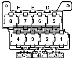
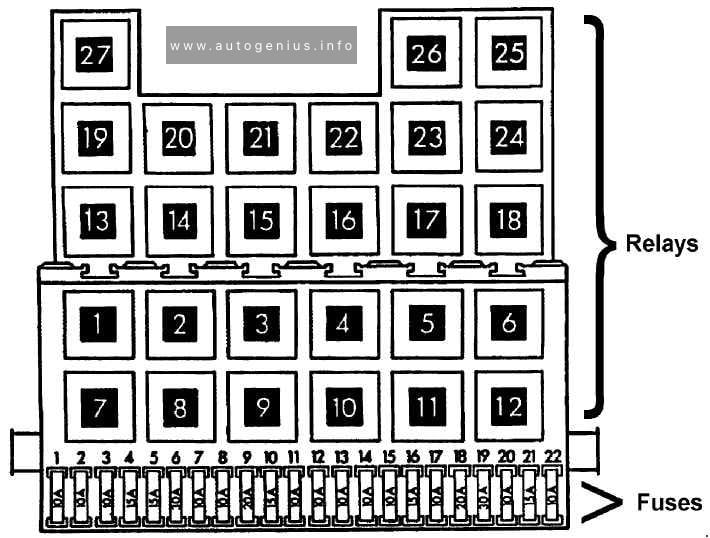
Relay carrier in engine compartment
| № | Relay |
|---|---|
| 1 | Automatic glow period control unit (diesel) |
| 1a | Fuel shut-off valve switch-off relay (petrol) |
| 1b | Coolant pump relay (petrol) |
| 2 | Starter relay 2 |
| 3 | Power steering control unit |
| 4 | Heated windscreen relay |
| 5 | Terminal 30 voltage supply relay |
| 6 | Starter inhibitor relay |
| 7a | Electric fuel pump 2 relay (diesel) |
| 7b | Coolant shut-off valve relay |
| 8a | Additional coolant pump relay |
| 8b | Fuel pump relay |
| 9 | Starter relay 1 |
| 10 | not assigned |
| 11 | Relay for reducing agent metering system |
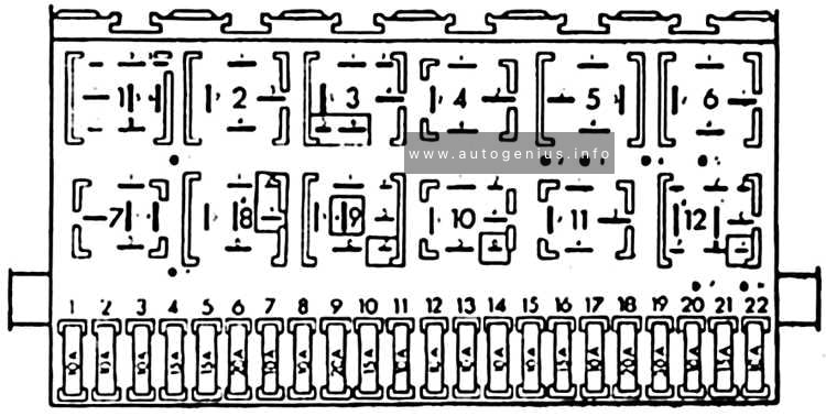
Relay carrier behind dash panel
| № | Relay |
|---|---|
| 1 | not assigned |
| 2a | Interior light relay |
| 2b | not assigned |
| 3a | Residual heat relay |
| 3b | Auxiliary heater relay |
| 4 | Headlight washer system relay |
| 5 | Isolation relay for powertrain CAN bus |
| 6 | Auxiliary coolant heater relay |
WARNING: Terminal and harness assignments for individual connectors will vary depending on vehicle equipment level, model, and market.