Chevrolet Trax (2018 – 2022) – fuse and relay box diagram
Year of production: 2018, 2019, 2020, 2021, 2022
The Chevrolet Trax is a compact crossover SUV that Chevrolet produced from 2013, with the 2018-2022 models representing the latter part of its first generation.
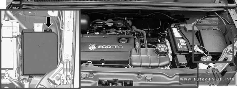
Passenger Compartment Fuse Box
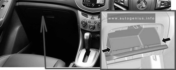
Fuse Box Location
The instrument panel fuse block is on the underside of the driver side instrument panel.
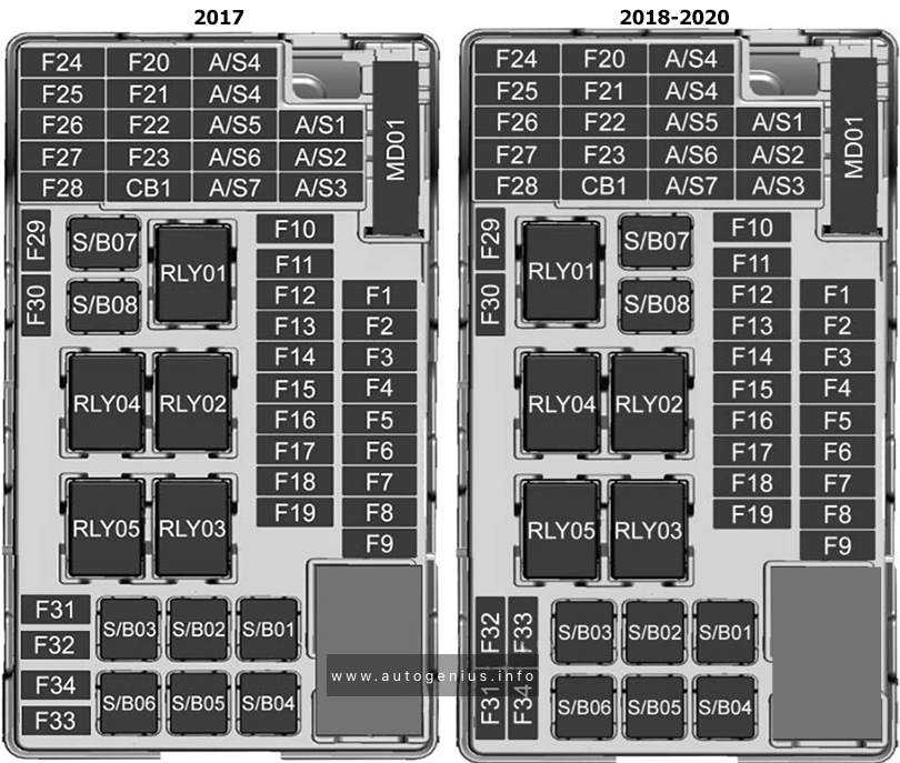
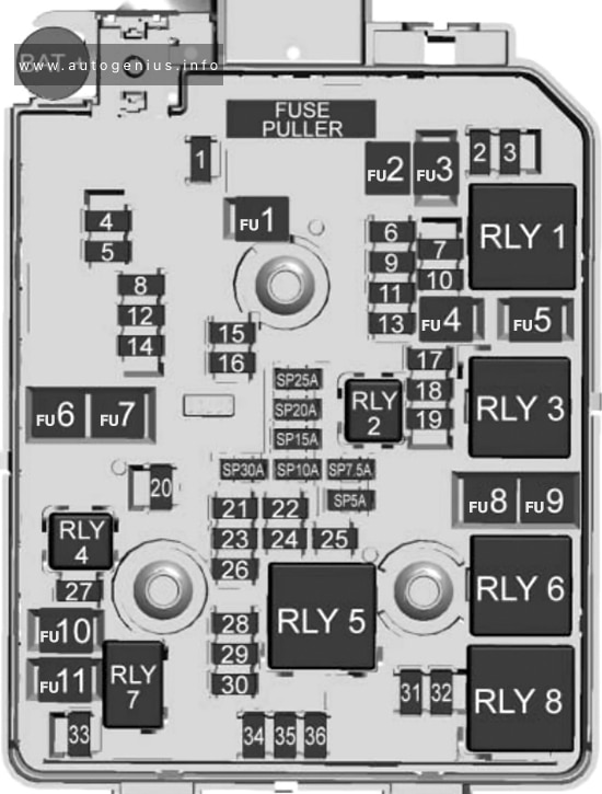
Fuse Box Diagram
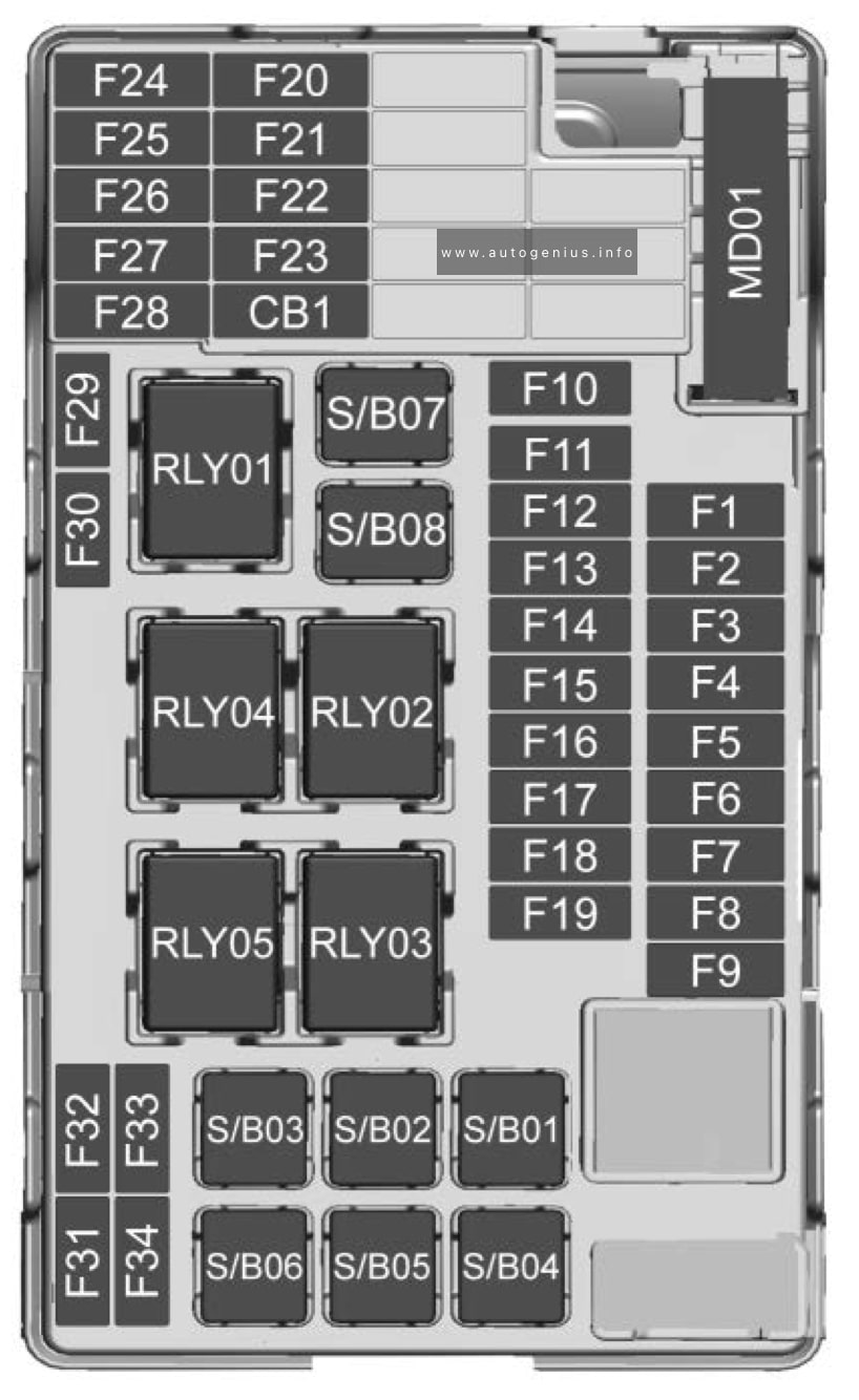
Assignment of the fuses in the passenger compartment
| Fuses | Description |
|---|---|
| F1 | Body control module 1 |
| F2 | Body control module 2 |
| F3 | Body control module 3 |
| F4 | Body control module 4 |
| F5 | Body control module 5 |
| F6 | Body control module 6 |
| F7 | Body control module 7 |
| F8 | Body control module 8 |
| F9 | Discrete logic ignition switch |
| F10 | Sensing diagnostic module battery |
| F11 | Data link connector |
| F12 | HVAC module/ICS |
| F13 | Liftgate relay |
| F14 | Central gate module |
| F15 | 2018-2020: Lane departure warning/GENTEX |
| F16 | — |
| F17 | 2018-2020: Electrical steering column lock |
| F18 | Parking assist module/Side blind zone alert |
| F19 | Body control module/Regulated voltage control |
| F20 | Clock spring |
| F21 | A/C/Accessory power outlet/ PRNDM |
| F22 | Auxiliary power outlet/DC front |
| F23 | 2018-2020: HVAC/MDL/ICS |
| F24 | — |
| F25 | OnStar module/ Eraglonass |
| F26 | 2018: Heated steering wheel. 2019-2021: Electric vacuum pump |
| F27 | 2018-2020: Instrument cluster/ Auxiliary heater/ Auxiliary virtual image display 2021-2022: Instrument cluster |
| F28 | 2018-2020: Trailer feed 2 |
| F29 | 2018-2020: Infotainment system |
| F30 | 2018-2020: DC DC 400W |
| F31 | Instrument cluster module battery |
| F32 | Silver box audio module/Navigation |
| F33 | 2018-2020: Trailer feed 1 |
| F34 | Passive entry/ Passive start |
| Midi Fuses | |
| M01 | 2018-2020: Positive temperature coefficient |
| S/B Fuses | |
| S/B01 | 2018: Passenger power seat 1 2019-2020: Powertrain cooling – 1 2021-2022: HVAC Aux heater – 1 |
| S/B02 | 2018: Not Used. 2019-2020: Powertrain cooling – 2 2021-2022: HVAC Aux heater – 2 |
| S/B03 | Front power windows |
| S/B04 | Rear power windows |
| S/B05 | Logistic mode relay/ DC DC 400W |
| S/B06 | Driver power seat |
| S/B07 | — |
| S/B08 | 2018-2020: Trailer interface module |
| Circuit Breaker | |
| CB1 | — |
| Relays | |
| RLY01 | Accessory/Retained accessory power |
| RLY02 | Liftgate |
| RLY03 | — |
| RLY04 | Blower |
| RLY05 | Logistic mode |
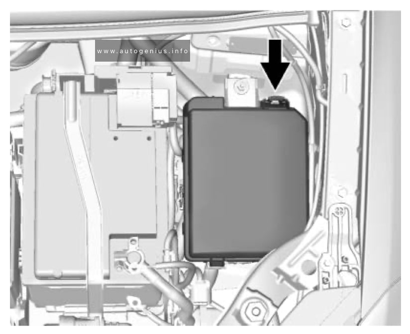
Engine Compartment Fuse Box
Fuse Box Location
Fuse Box Diagram
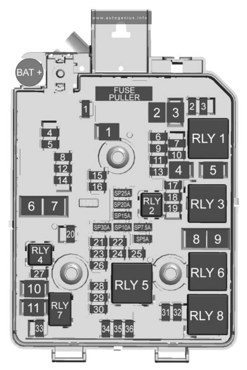
Assignment of the fuses in the engine compartment
| № | Description |
|---|---|
| Mini Fuses | |
| 1 | Sunroof |
| 2 | 2018-2020: Exterior rearview mirror switch/ Driver side power window/ Rain sensor/ Universal garage door opener 2021-2022: Exterior rearview mirror switch/ Driver side power window/ Rain sensor |
| 3 | Canister vent solenoid |
| 4 | — |
| 5 | Electronic brake control module valve |
| 6 | 2018-2020: Intelligent battery sensor |
| 7 | 208-2021: Electric steering column lock |
| 8 | Transmission control module/FICM |
| 9 | Automatic occupancy sensing module |
| 10 | 2018-2020: Headlamp leveling switch/ Headlamp leveling motor/ Rear vision camera/ Interior rearview mirror 2021: Rear vision camera/ Interior rearview mirror 2022: Rear vision camera |
| 11 | Rear wiper |
| 12 | Rear window defogger |
| 13 | Power lumbar switch |
| 14 | Exterior rearview mirror heater |
| 15 | Fuel system control module batterv |
| 16 | Heated seat module/ Memory module |
| 17 | 2018-2020: TIM DC DC converter/Fuel system control module RC/ Compass module 2021: Fuel system control module RC/ Blow byheater 2022: Fuel system control module RC |
| 18 | Engine control module RC/ Transmission control module RC/ FICM RC |
| 19 | 2018-2020: Fuel pump |
| 20 | — |
| 21 | Fan relay (auxiliary BEC) |
| 22 | — |
| 23 | Ignition coil/ Injector coil |
| 24 | Washer pump |
| 25 | 2018-2020: Automatic headlamp leveling |
| 26 | EMS Var 1 |
| 27 | — |
| 28 | 2021-2022: Ignition 3 |
| 29 | Engine control module powertrain/ Ignition 1/lgnition 2 |
| 30 | EMS Var 2 |
| 31 | Left high-beam headlamp |
| 32 | Right high-beam headlamp |
| 33 | Engine control module battery |
| 34 | Horn |
| 35 | A/C clutch |
| 36 | 2018-2020: Front fog lamps |
| J-Case Fuses | |
| 1 | Electronic brake control module pump |
| 2 | Front wiper |
| 3 | Linear power module blower |
| 4 | IEC RC |
| 5 | — |
| 6 | — |
| 7 | — |
| 8 | Cooling fan low – mid |
| 9 | Cooling fan – high |
| 10 | 2018-2021: EVP |
| 11 | Starter solenoid |
| U-Micro Relays | |
| 2 | 2018-2021: Fuel pump |
| 4 | — |
| HC-Micro Relays | |
| 7 | Starter |
| Mini Relays | |
| 1 | Run/Crank |
| 3 | Cooling fan – mid |
| 4 | — |
| 5 | Powertrain relay |
| 8 | Cooling fan – low |
| HC-Mini Relays | |
| 6 | Cooling fan – high |
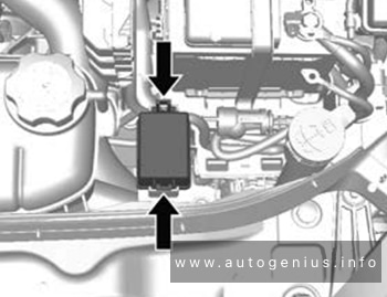
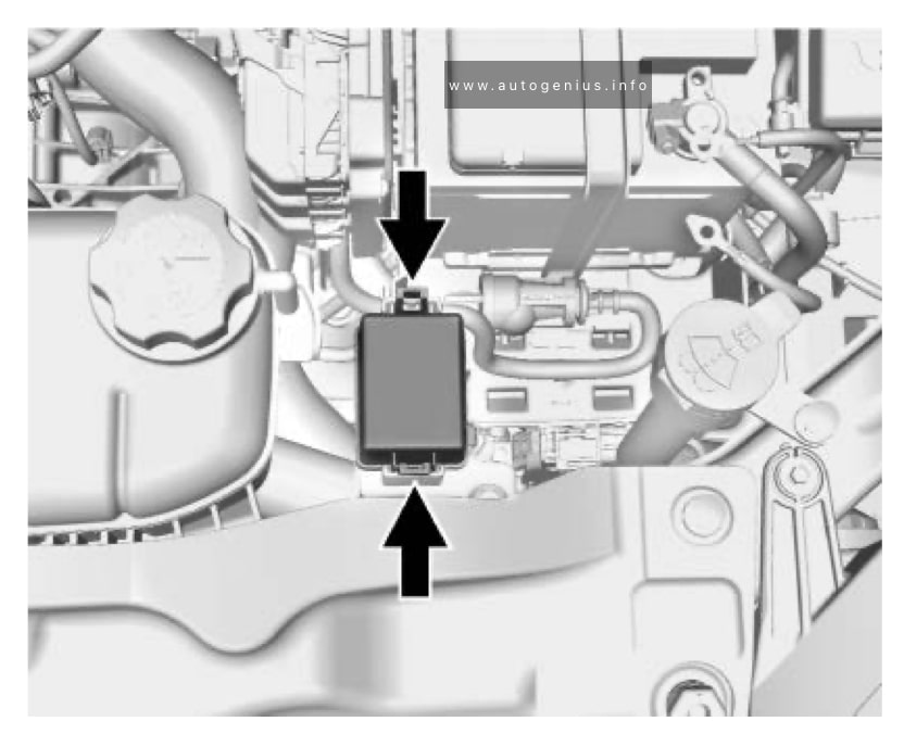
Auxiliary relay box
Relay Box Location
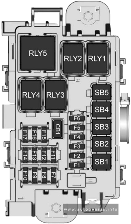
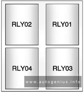
Relay Box Diagram
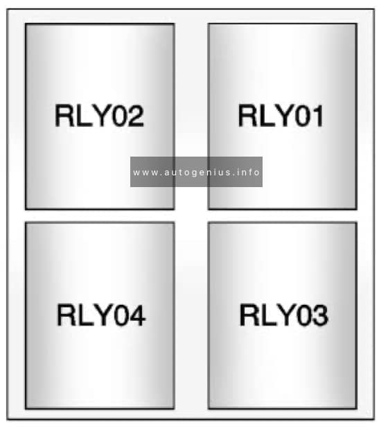
Assignment of the fuses in the auxiliary relay box
| Relays | Usage |
|---|---|
| 01 | 2018-2020: Electric vacuum pump |
| 02 | Cooling fan control 1 |
| 03 | Cooling fan control 2 |
| 04 | 2018-2020: Trailer (1.4L only) |
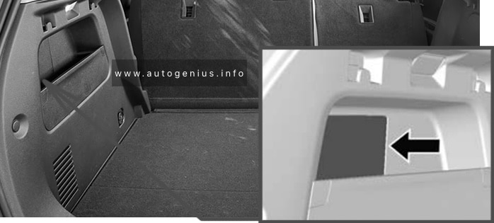
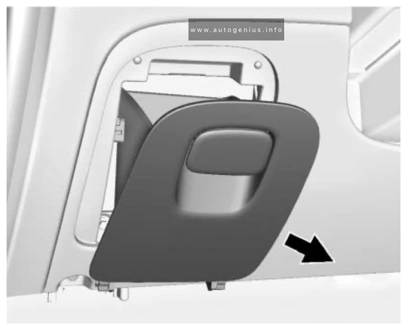
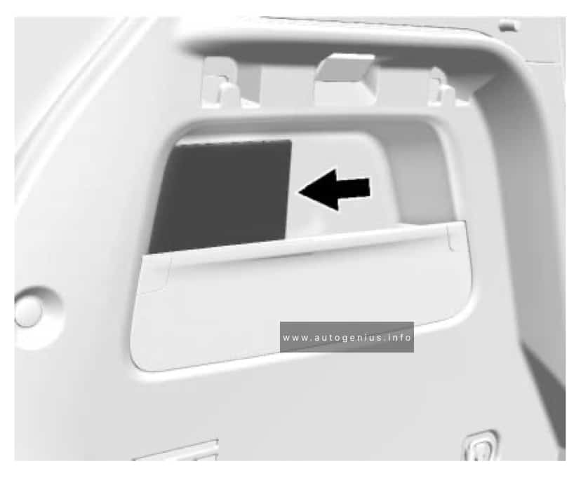
Rear Compartment Fuse Box
Fuse Box Location
The rear compartment fuse box is located in the passenger side.
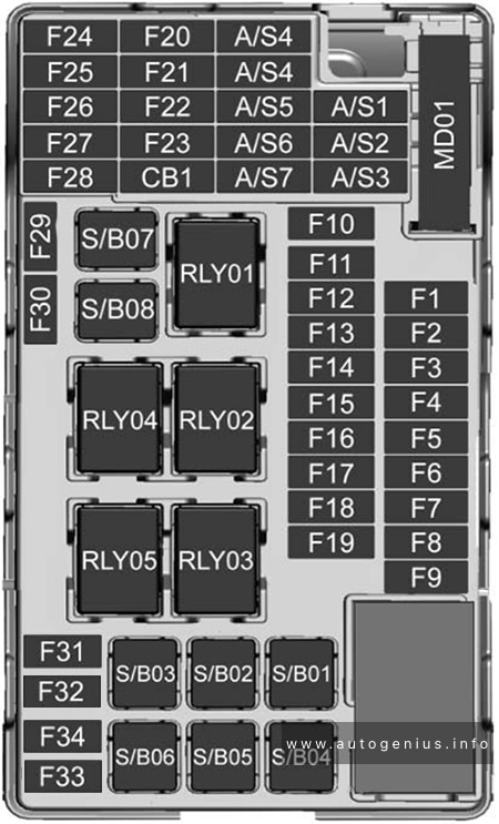
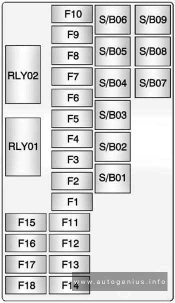
Fuse Box Diagram
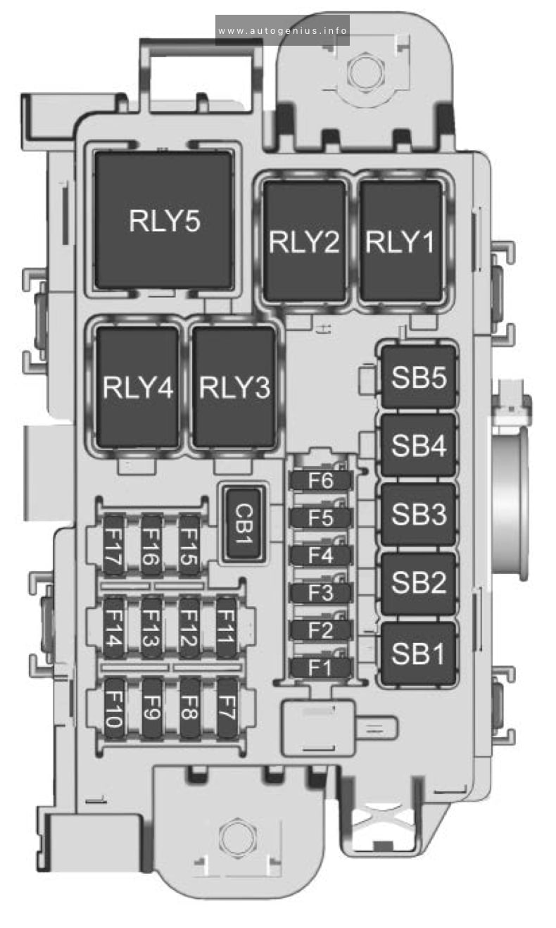
Assignment of the fuses in the rear compartment
| Fuses | Description |
|---|---|
| F1 | 2018-2020: Amplifier audio |
| F2 | Rear drive control module |
| F3 | — |
| F4 | — |
| F5 | — |
| F6 | — |
| F7 | — |
| F8 | — |
| F9 | — |
| F10 | — |
| F11 | — |
| F12 | — |
| F13 | |
| F14 | — |
| F15 | _ |
| F16 | — |
| F17 | — |
| S/B Fuses | |
| S/B1 | 2018-2020: DC-DC transformer 400W |
| S/B2 | 2018-2020: DC-DC transformer 400W |
| S/B3 | DC/AC inverter module |
| S/B4 | — |
| S/B5 | — |
| Relays | |
| RLY01 | — |
| RLY02 | — |
| RLY03 | — |
| RLY04 | — |
| RLY05 | — |
| Circuit Breakers | |
| CB1 | — |
WARNING: Terminal and harness assignments for individual connectors will vary depending on vehicle equipment level, model, and market.