Volkswagen ID. Buzz (2022 – 2024) – fuses and relay box diagram
Year of production: 2022, 2023, 2024
The Volkswagen ID. Buzz, a battery-electric minivan, has been available since 2022. In this article, you will find fuse box diagrams for the 2022, 2023 and 2024 Volkswagen ID. Buzz, along with information on the locations of the fuse panels within the vehicle and details about the function of each fuse (fuse layout) and relay.
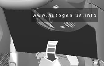
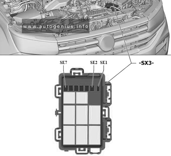
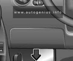
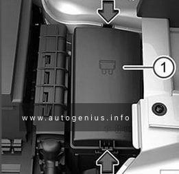
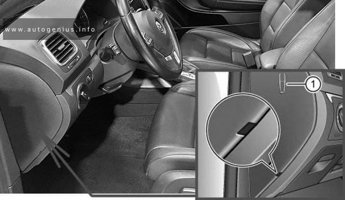
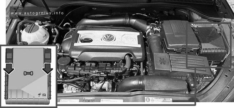
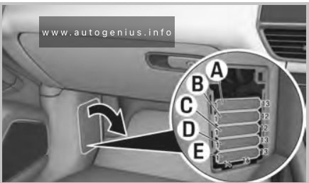
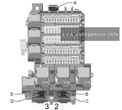
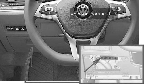
Passenger compartment
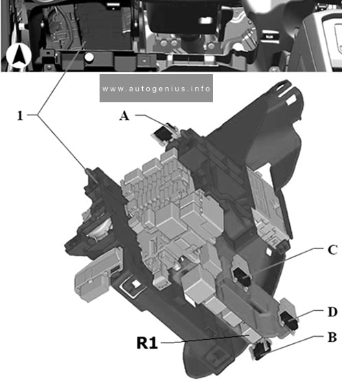
Fuse Box Location
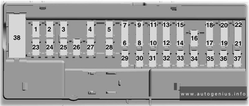
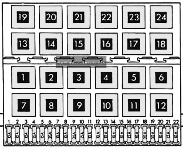
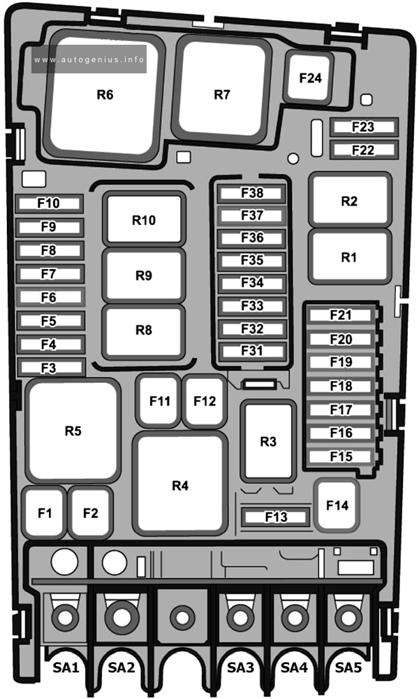
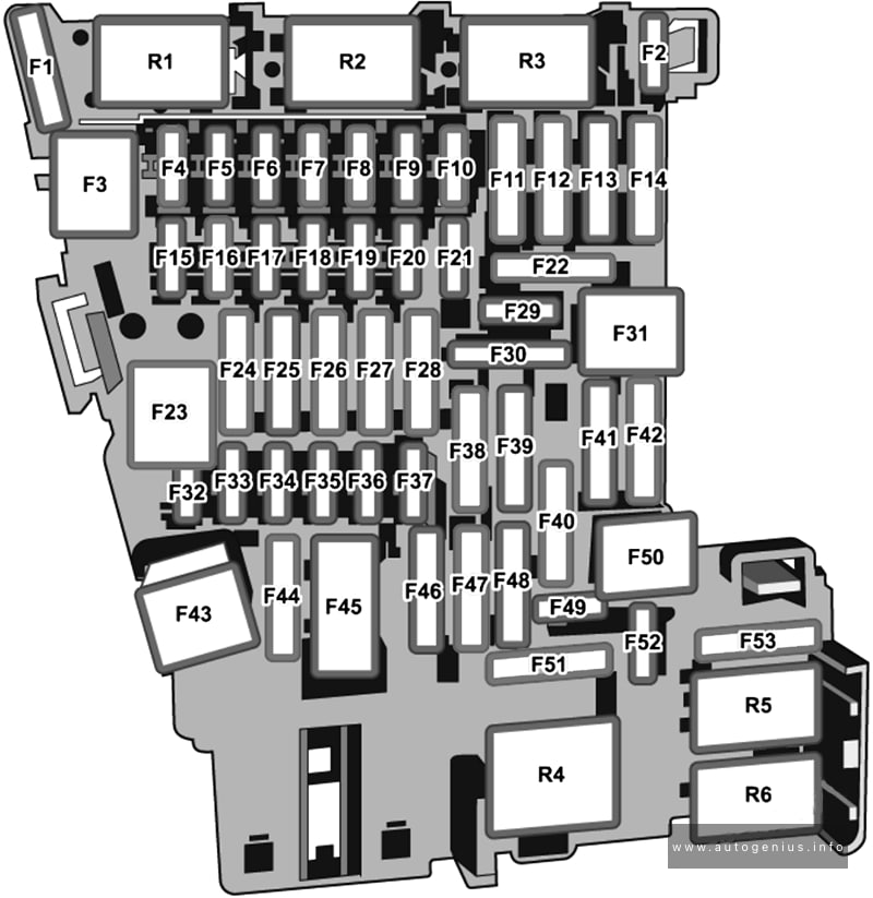
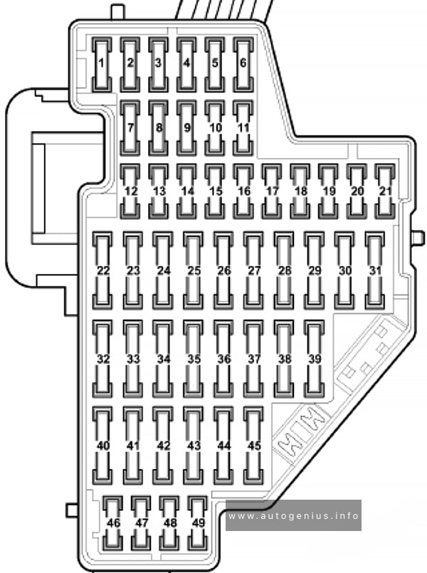
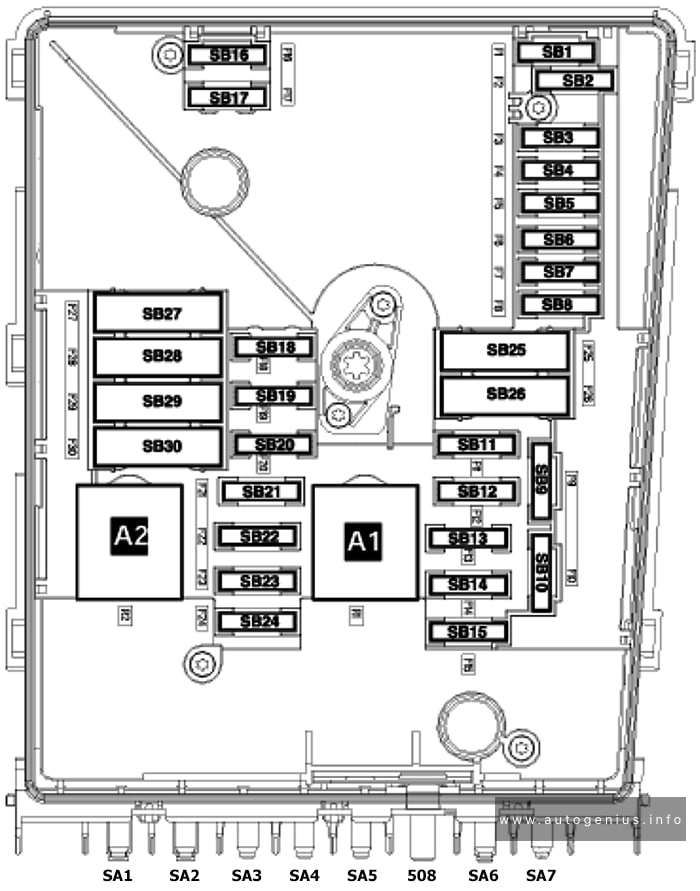
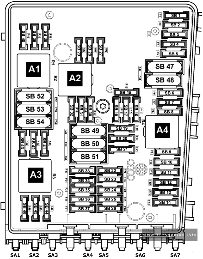
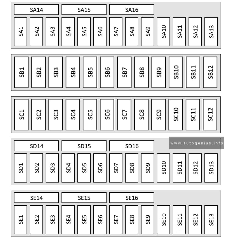
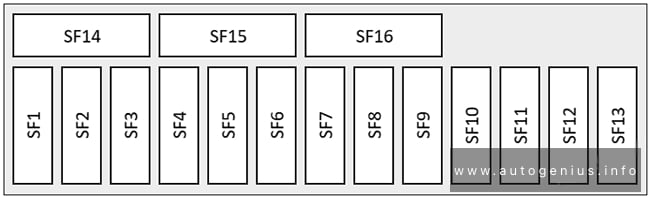
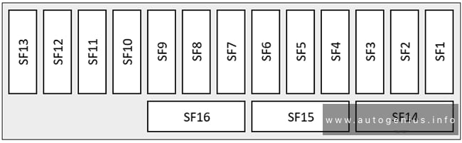
Fuse Box Diagram (-SC-)
Assignment of the fuses and relays in the instrument panel (-SC-)
| № | Amps | Function / component |
|---|---|---|
| SC1 | 60A | Brake servo |
| SC2 | 15A | Airbag control unit |
| SC3 | 25A | Onboard supply control unit |
| SC4 | 30A | Front left windscreen wiper motor |
| SC5 | 30A | Front right windscreen wiper motor |
| SC6 | 25A | Onboard supply control unit |
| SC7 | 30A | Heater and air conditioning system control unit |
| SC8 | 20A | 12V socket (Cargo version) 12V socket 4 (Cargo version) |
| SC9 | 30A | Driver door control unit (LHD) Front passenger door control unit (RHD) |
| SC10 | 25A | Front left headlight |
| SC11 | 25A | Front right headlight |
| SC12 | 40A | Heated windscreen relay Heated windscreen Left heating circuit |
| SC13 | 40A | Onboard supply control unit |
| SC14 | 50A | ABS control unit |
| SC15 | – | – |
| SC16 | – | – |
| SC17 | 20A | Cigarette lighter, sockets |
| SC18 | 10A | Alarm horn |
| SC19 | 5A | Emergency call module control unit and communication unit Control unit with display unit for driver information system Charging unit 1 for mobile devices Aerial amplifier for mobile telephone |
| SC20 | 7.5A | Centre switch module in dash panel Operating unit for window regulator in driver door Operating unit for lighting Humidity sender for air conditioning system Rain and light sensor Anti-theft alarm sensor Dynamic light strip 3 for information in dash panel Diagnostic connection Front roof module |
| SC21 | 7.5A | Internet access control unit |
| SC22 | 10A | Engine/motor control unit |
| SC23 | 7.5A | Adaptive cruise control unit |
| SC24 | 7.5A/10A | USB connection 1 (PR №U9C) USB connection 1 (PR №U9E/U9G/A8B/A8C/A9Q) USB charging socket 3 (PR №U9E/U9G/A8B/A8C/A9Q) |
| SC25 | 30A | Front left seat belt (LHD) Front right seat belt (RHD) |
| SC26 | 30A | Onboard supply control unit |
| SC27 | 30A | Front right seat belt (LHD) Front left seat belt (RHD) |
| SC28 | – | – |
| SC29 | 30A | Fresh air blower control unit |
| SC30 | 30A | Control unit 1 for information electronics |
| SC31 | 30A | ABS control unit |
| SC32 | 30A | Front passenger door control unit (LHD) Driver door control unit (RHD) |
| SC33 | – | – |
| SC34 | 15A | Heater and air conditioning system control unit |
| SC35 | 40A | Heated windscreen relay 2 Heated windscreen Right heating circuit |
| SC36 | 40A | DC/AC converter with socket, 12V – 230V |
| SC37 | 50A | Radiator fan Jump-start connection point for low-voltage electrical system, positive terminal |
| SC38 | 7.5A | Control unit for front left massage seat Control unit for front right massage seat |
| SC39 | 15A | Steering column electronics control unit Heated steering wheel |
| SC40 | 7.5A | Anti-theft alarm Control unit for electronic steering column lock Entry and start authorisation control unit Control unit 2 for break-in protection Control unit 3 for break-in protection |
| SC41 | 7.5A | Data bus diagnostic interface |
| SC42 | 15A | Horn relay Left horn |
| SC43 | 7.5A | ABS control unit Main relay |
| SC44 | 7.5A | Front camera for driver assist systems |
| SC45 | 7.5A | Steering column electronics control unit |
| SC46 | 7.5A | Display unit for front information display and operating unit control unit |
| SC47 | 10A | Engine sound generator module 1 |
| SC48 | – | – |
| SC49 | 10A | Engine/motor control unit |
| SC50 | 7.5A | Radiator fan |
| SC51 | 10A | PTC heater element 3 Coolant pump for high-voltage battery |
| SC52 | 15A | Control motor for radiator roller blind Coolant pump for low-temperature circuit |
| SC53 | – | – |
| SC54 | – | – |
| SC55 | – | – |
| SC56 | – | – |
| SC57 | – | – |
| SC58 | – | – |
| SC59 | 7.5A | Automatic anti-dazzle interior mirror |
| SC60 | 7.5A | Diagnostic connection |
| SC61 | 7.5A | Power and control electronics for electric drive |
| SC62 | 10A | USB charging socket 1 USB charging socket for seat row 2, left USB charging socket for seat row 2, right USB charging socket for seat row 3, left USB charging socket for seat row 3, right USB charging socket in headlining USB charging socket 3 |
| SC63 | – | – |
| SC64 | – | – |
| SC65 | – | – |
| SC66 | 15A | Rear window wiper motor Rear seat heating |
| SC67 | – | – |
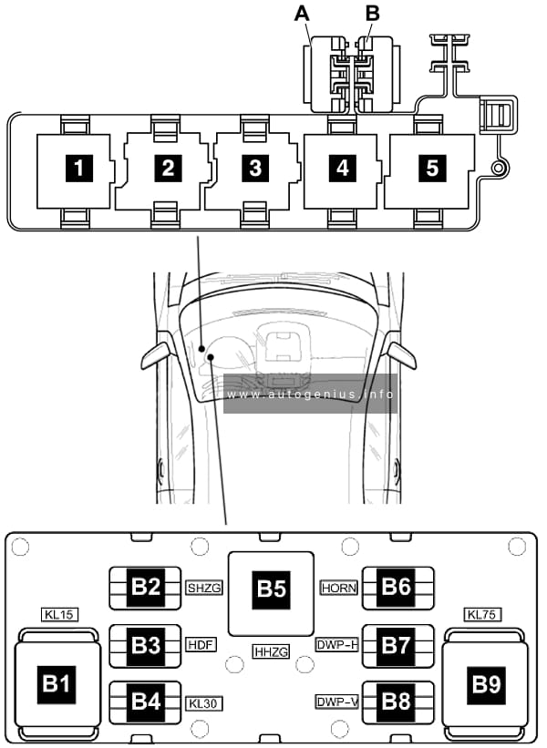
| R1 | Main relay | |
| R2 | Terminal 15 voltage supply relay | |
| R3 | – | |
| R4 | Heated windscreen relay | |
| R5 | Heated windscreen relay 2 | |
| R6 | Horn relay |
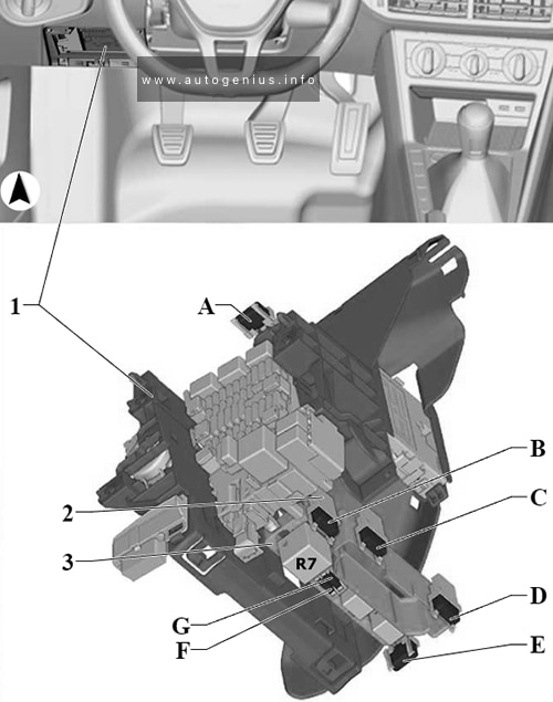
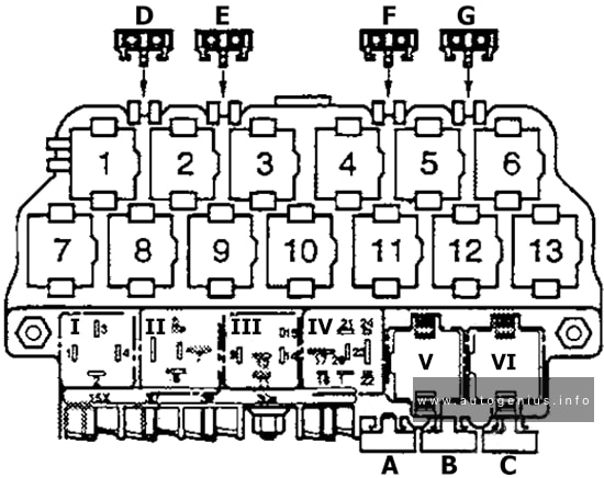
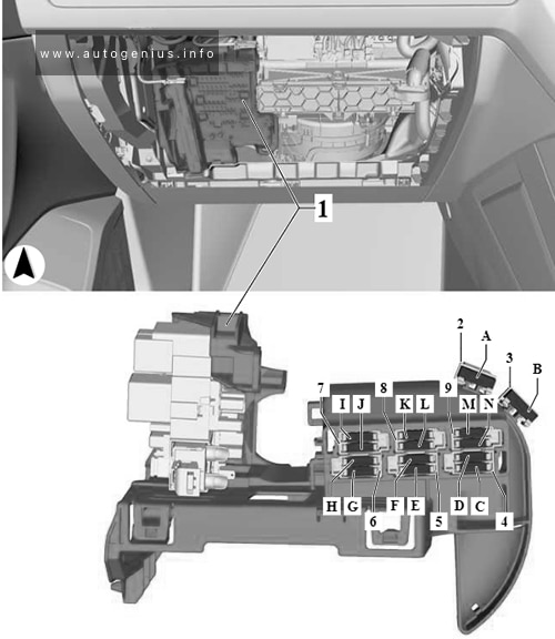
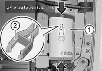
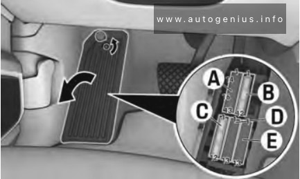
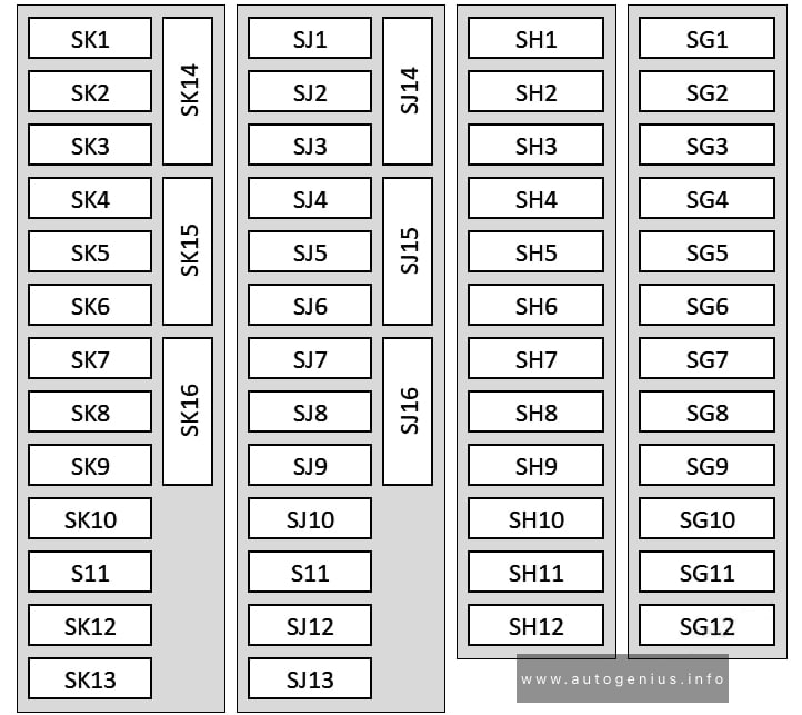
Individual fuses
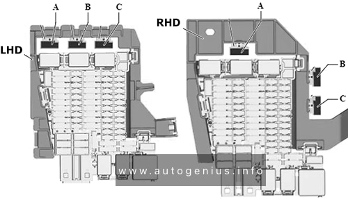
Assignment of the fuses in the passenger compartment (indivudual fuses)
| № | Amps | Function / component |
|---|---|---|
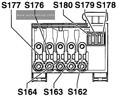
| A | – | |
| B | 20A | Front passenger seat adjustment with memory control unit (-ST1-) |
| C | 20A | Seat and steering column adjustment control unit with memory (-ST2-) |
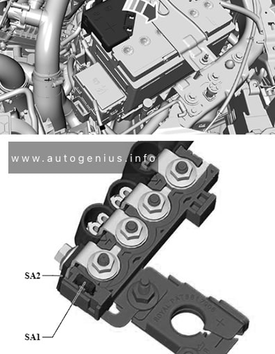
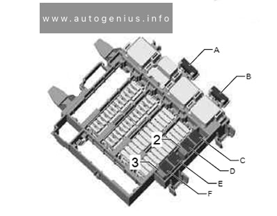
Main Fuses (-SA-)

Assignment of the fuses in the passenger compartment (main fuses (-SA-))
| № | Amps | Function / component |
|---|---|---|
| 508 | – | Battery |
| SA1 | 350A | Voltage converter |
| SA2 | 100A | Battery monitor control unit Power steering control unit |
| SA3 | 100A | Fuse holder D Fuse holder E Fuse carrier 4 -ST4- Fuse carrier 6 -ST6- |
| SA4 | – | – |
| SA5 | 125A | Fuse holder C |
| SA6 | 125A | Fuse holder C |
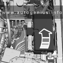
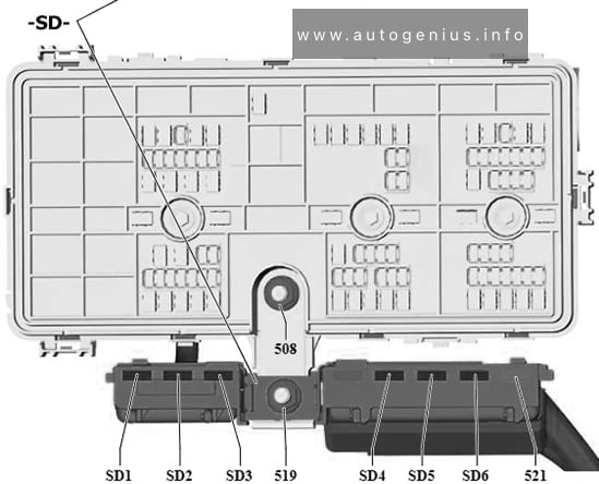
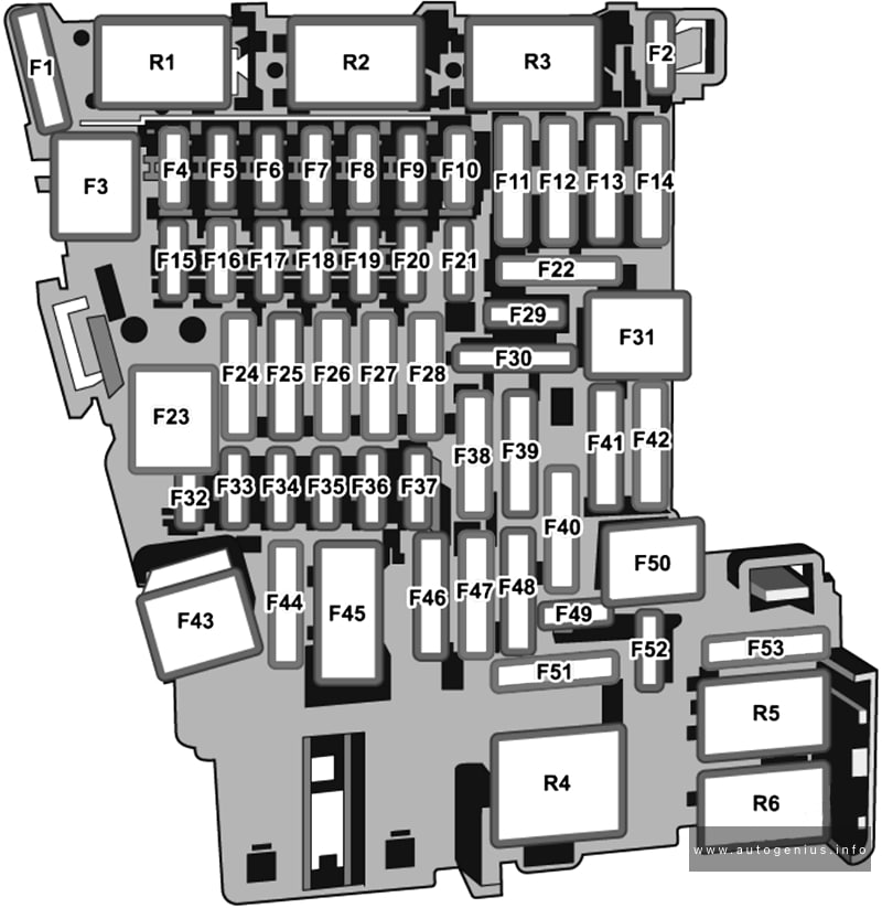
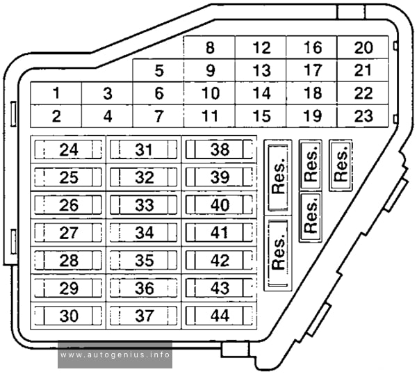
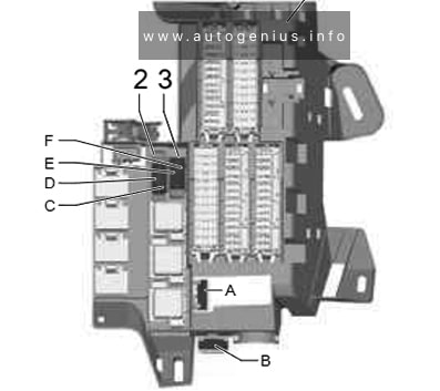
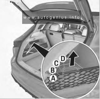
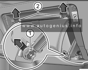
Load Compartment Fuse Box
Fuse Box Location

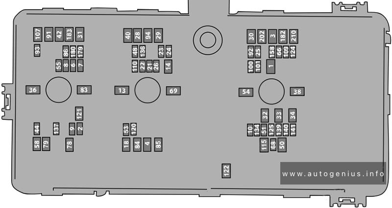
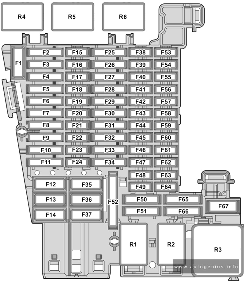
Fuse Box Diagram (-SD-/-SE-)
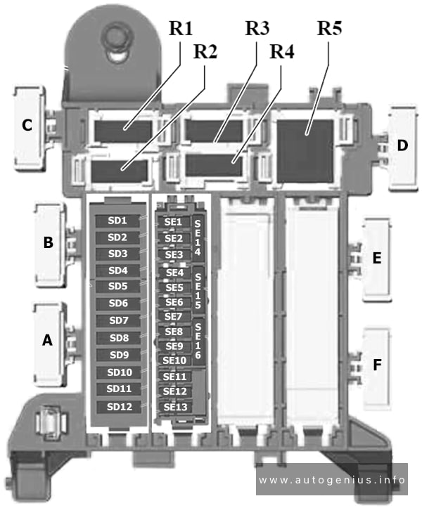
Assignment of the fuses in the load compartment (-SD-/-SE-)
| № | Amps | Function / component |
|---|---|---|
| SD1 | 30A | Trailer detector control unit |
| SD2 | 7.5A | Left tail light cluster Centre tail light cluster Left brake light bulb 2 |
| SD3 | 20A | Trailer detector control unit |
| SD4 | – | – |
| SD5 | – | – |
| SD6 | 30A | Heated rear window relay Rear window Frequency modulation (FM) frequency filter in positive wire |
| SD7 | 20A | Trailer detector control unit |
| SD8 | 30A | Trailer detector control unit |
| SD9 | 20A | 12V socket 3 |
| SD10 | – | – |
| SD11 | 15A | High-voltage battery 1 Battery regulation control unit Maintenance connector for high-voltage system |
| SD12 | – | – |
| SE1 | 7.5A | Interior monitor send and receive module 2 Vehicle interior temperature sensor Heated rear window relay Rear lid power opening control unit Control unit 4 for break-in protection Control unit 5 for break-in protection |
| SE2 | 7.5A | Right tail light cluster Centre tail light cluster Right brake light bulb 2 |
| SE3 | 15A | Left sliding door relay Rear left sliding door lock unit |
| SE4 | – | – |
| SE5 | 7.5A | Control unit for overhead view camera Reversing camera |
| SE6 | – | – |
| SE7 | 15A | Right sliding door relay Rear right sliding door lock unit |
| SE8 | 7.5A | Air conditioning system relay Air quality sensor Air conditioner compressor |
| SE9 | 10A | USB charging socket for seat row 2, left USB charging socket for seat row 2, right |
| SE10 | 10A | USB charging socket for seat row 3, left USB charging socket for seat row 3, right |
| SE11 | 15A | Voltage converter Charging unit 1 for high-voltage battery Power and control electronics for electric drive |
| SE12 | 7.5A | Parking aid control unit Lane change assist control unit Lane change assist control unit 2 |
| SE13 | – | – |
| SE14 | – | – |
| SE15 | – | – |
| SE16 | 30A | Rear lid control unit |
| A (ST6) | 40A | ID.BUZZ CARGO: Rear driver side door control unit (LHD) Passenger side rear door control unit (RHD) |
| B (ST4) | 40A | ID.BUZZ CARGO: Rear passenger side door control unit (LHD) Rear driver side door control unit (RHD) |
| C | – | – |
| D | – | – |
| E (ST4) | 40A | ID.BUZZ: Rear passenger side door control unit (LHD) Rear driver side door control unit (RHD) |
| F (ST6) | 40A | ID.BUZZ: Rear driver side door control unit (LHD) Passenger side rear door control unit (RHD) |
| G | – | – |
| R1 | Air conditioning system relay | |
| R2 | – | |
| R3 | Left sliding door relay | |
| R4 | Right sliding door relay | |
| R5 | Heated rear window relay |
WARNING: Terminal and harness assignments for individual connectors will vary depending on vehicle equipment level, model, and market.