Year of production: 2014, 2015, 2016, 2017, 2018, 2019, 2020
This article provides the Volkswagen e-Golf, produced from 2014 to the 2020. It provides fuse box diagrams for the Volkswagen e-Golf models from 2014, 2015, 2016, 2017, 2018, 2019, 2029, 2021, and 2022, along with details on the location of the fuse panels within the vehicle. Additionally, it explains the fuse and relay assignments (fuse layout).
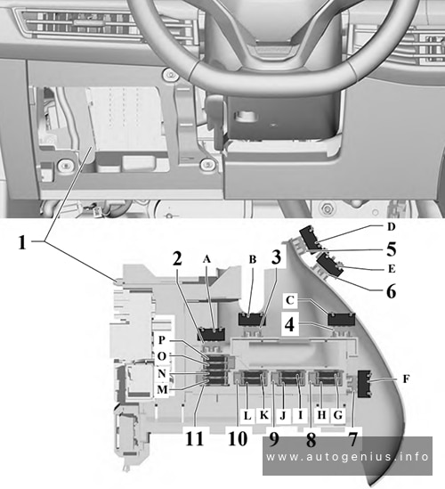
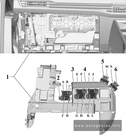
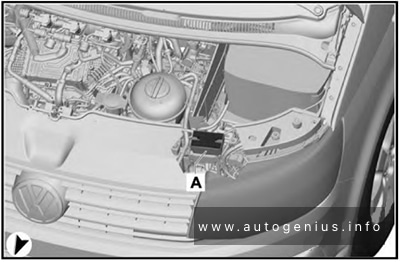
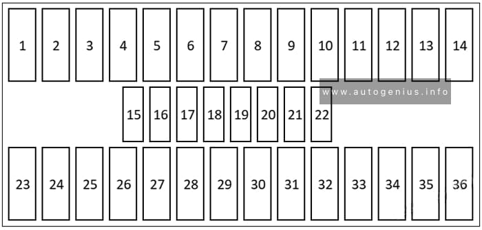
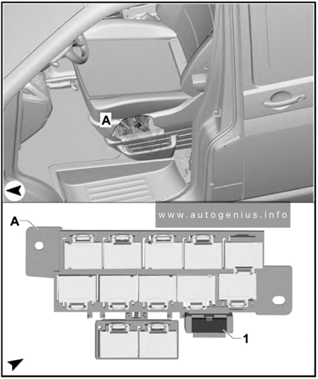
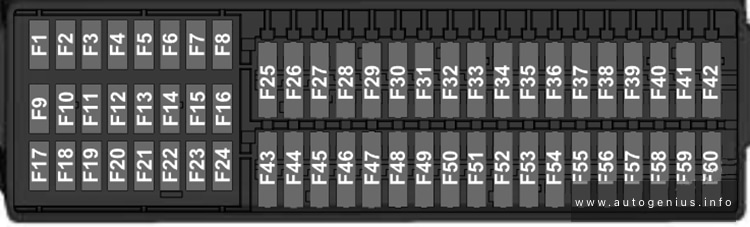
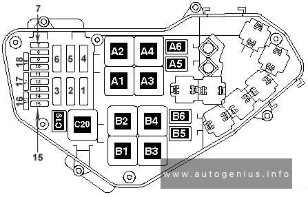
Assignment of the fuses in the passenger compartment (instrument panel -SC-)
№
Amps
Function / Component
SC1
–
–
SC2
–
–
SC3
–
–
SC4
10A
2014-2017:
Vehicle electrical system control module
– Anti-theft alarm system
SC4
7.5A/10A
2018-2020:
Alarm horn
SC5
5A/7.5A
Data bus on board diagnostic interface
SC6
5A
2014-2015:
Anti-theft alarm system sensor2015-2020:
Selector lever
SC7
10A
2014-2015:
Heater and A/C controls
Climatronic control module
Selector lever
Rear window defogger relay2015-2020:
Heater and A/C controls
Climatronic control module
Rear window defogger relay
2014-2017:
Left front seat belt tensioner control module
SC11
40A
2017-2020:
Vehicle electrical system control module
– Left front headlamp
SC12
20A
Information electronics control module 1
SC13
10A
2014-2017:
High-voltage battery 1
High-voltage system maintenance connector
SC13
25A
2017-2020:
Left front seat belt tensioner control module
SC14
30A
Fresh air blower control module
SC15
10A
Electronic steering column lock control module
SC16
7.5A
Mobile communication 2-way signal amplifier
Telephone baseplate
Voltage converter for USB charge module (2014-2015)
USB distributor
Chip card reader control module
TV tuner
SC17
5A
Instrument cluster
Control module for emergency call module and communication unit
Telematics Control Module for Real-Time Monitoring (2018-2020 vehicles with China equipment)
SC18
7.5A
Rearview camera
Release button in rear lid handle
SC19
7.5A
Access/start system interface
SC20
5A
High-voltage battery charging voltage control module
SC21
–
–
SC22
–
–
SC23
40A
2014-2017:
Vehicle electrical system control module
– Right front headlamp
SC24
40A
2017-2020:
Vehicle electrical system control module
– Right front headlamp
SC25
30A
Driver Door Control Module (LHD)
Left Rear Window Regulator Motor (LHD)
Front Passenger Door Control Module (RHD)
Right Rear Window Regulator Motor (RHD)
SC26
30A
Vehicle electrical system control module
– Front heated seat
SC27
30A
2014-2017:
Digital sound system control module2017-2020:
Vehicle electrical system control module
– Terminal 30
SC28
–
–
SC29
–
–
SC30
10A
2017-2020:
High-voltage battery 1
High-voltage system maintenance connector
SC31
40A
2014-2017:
Vehicle electrical system control module
– Left front headlamp
SC32
7.5A/10A
Driver assistance systems front camera
Distance regulation control module
Parking Aid Control Module
Parallel Parking Assistance Control Module
Blind spot detection control module
Blind spot detection control module 2
SC33
5A/7.5A
Airbag control module
Front passenger airbag -disabled- indicator lamp
Diagnostic connection
Headlamp Range Control and Instrument Illumination Regulator Cornering lamp and headlamp range control module
SC36
5A
2014-2018:
Right LED headlamp power output module 1
SC36
10A
2018-2020:
Right front headlamp
– Right LED headlamp power output module 1
– Right Headlamp Power Output Module
– Left Light Control Module
SC37
5A
2014-2018:
Left LED headlamp power output module 1
SC37
10A
2018-2020:
Left front headlamp
– Left LED headlamp power output module 1
– Left Headlamp Power Output Module
– Right Light Control Module
SC38
–
–
SC39
30A
Front Passenger Door Control Module (LHD)
Right Rear Window Regulator Motor (LHD)
Driver Door Control Module (RHD)
Left Rear Window Regulator Motor (RHD)
SC40
20A
Cigarette Lighter
12V socket -U5-
12V socket 2 -U18-
From the factory, fuse SC40 is supplied by terminal 15 and can be supplied by terminal 30 instead, if equipment is connected to the socket or the cigarette lighter, make sure the equipment is disconnected from the power supply when the engine is off to prevent the battery from draining.
SC41
25A
Right front seat belt tensioner control module
SC42
40A
Vehicle electrical system control module
– Central locking system
SC43
30A
2014-2017:
Vehicle electrical system control module
– Terminal 302017-2020:
Digital sound system control module
SC44
–
–
SC45
15A
Left Front Seat Adjustment Control Head
SC46
–
–
SC47
15A
Rear window wiper motor
SC48
7.5A
Engine sound generator control module
SC49
5A/7.5A
High-voltage battery charging voltage control module
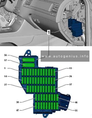
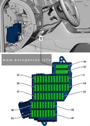
Volkswagen Golf VIII (MK8; 2020 – 2024) – fuse and relay box diagram
Year of production: 2020, 2021, 2022, 2023, 2024
This article provides the eighth-generation Volkswagen Golf (MK8), produced from 2020 to the present. It provides fuse box diagrams for the Volkswagen Golf VIII models from 2020, 2021, and 2022, along with details on the location of the fuse panels within the vehicle. Additionally, it explains the fuse and relay assignments (fuse layout).
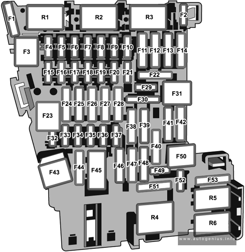
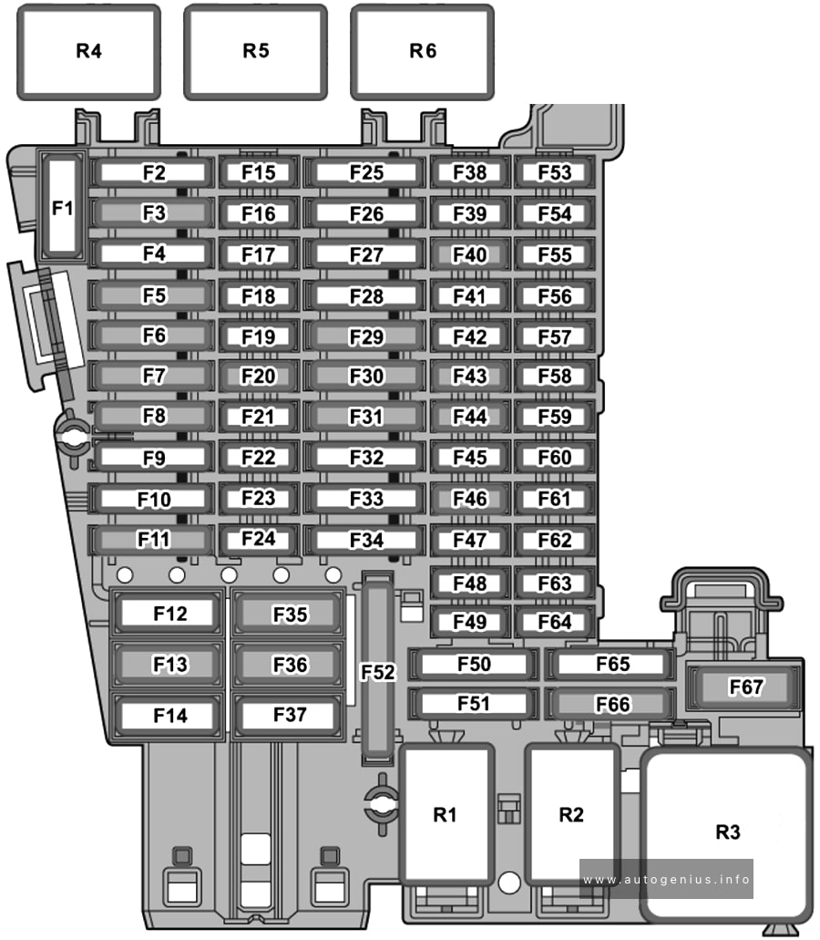
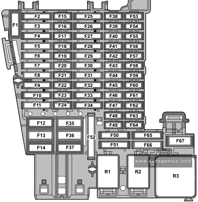
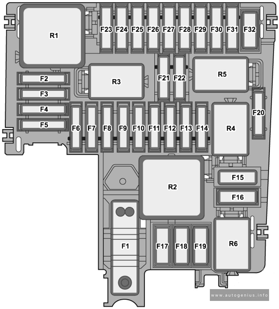
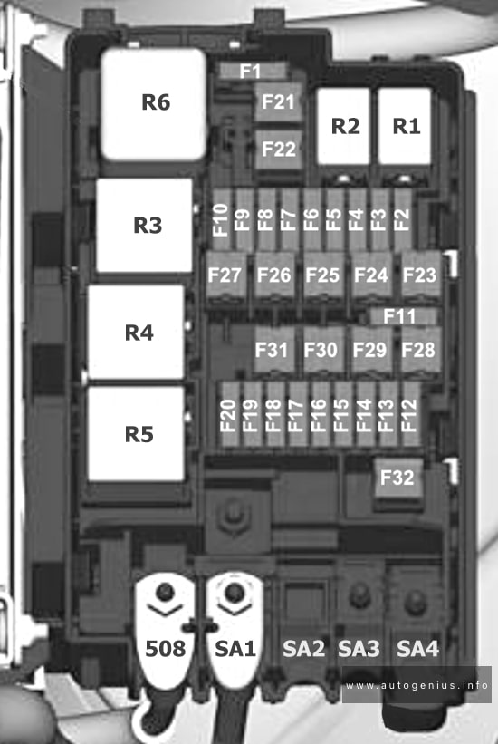
Passenger Compartment Fuse Box (Fuse Panel C -SC-)
Assignment of the fuses in the passenger compartment (instrument panel)
№
Amps
Function / component
SC1
–
–
SC2
–
–
SC3
25 A
Trailer detector control unit
SC4
20 A
Control unit for reducing agent heater (diesel)
SC5
25 A
Parking lock actuator
SC6
30 A
Onboard supply control unit
Interior lighting
SC7
30 A
Heater and air conditioning system control unit
Seat heating
SC8
20 A
Sliding sunroof adjustment control unit
SC9
30 A
Driver door control unit (left-hand drive models)
Front passenger door control unit (right-hand drive models)
Rear driver side window regulator motor (left-hand drive models)
Rear passenger side window regulator motor (right-hand drive models)
SC10
–
–
SC11
15 A
Trailer detector control unit
SC12
40 A
Onboard supply control unit
Exterior lighting (left-side)
SC13
40 A
Onboard supply control unit
Central locking
SC14
30 A
Digital sound package control unit
SC15
–
–
SC16
7.5 A
Airbag control unit
SC17
10 A
Relay for reducing agent metering system
SC18
7.5 A
Interface for entry and start system
Driver exterior door handle (left-hand drive models)
Front passenger exterior door handle (right-hand drive models)
Control unit 2 for break-in protection
Control unit 3 for break-in protection
Control unit 4 for break-in protection
Control unit 5 for break-in protection
Control unit for electronic steering column lock
SC19
7.5 A
Dash panel insert
Emergency call module control unit and communication unit
SC20
7.5 A
Internet access control unit
Chip card reader control unit (Japan)
TV tuner (Japan)
Telephone bracket
Transmission and reception stabilisation control unit
USB connection 1
SC21
7.5 A
Lane change assist control unit
Lane change assist control unit 2
Driver side exterior mirror
Passenger side exterior mirror
Rear lid handle
SC22
–
–
SC23
–
–
SC24
15 A
All-wheel drive control unit
SC25
25 A
Front left seat belt (left-hand drive models)
Front right seat belt (right-hand drive models)
SC26
30 A
Driver door control unit (right-hand drive models)
Front passenger door control unit (left-hand drive models)
Rear driver side window regulator motor (right-hand drive models)
Rear passenger side window regulator motor (left-hand drive models)
SC27
25 A
Front right seat belt (left-hand drive models)
Front left seat belt (right-hand drive models)
SC28
–
–
SC29
15 A
Trailer detector control unit
SC30
30 A
Control unit 1 for information electronics
SC31
25 A
Trailer detector control unit
SC32
25 A
Operating and display unit for rear air conditioning system
Rear seat heating
SC33
–
–
SC34
–
–
SC35
40 A
Onboard supply control unit
Exterior lighting (right-side)
SC36
40 A
Fresh air blower control unit
SC37
–
–
SC38
–
–
SC39
10 A
Steering column electronics control unit
SC40
7.5 A
Alarm horn
SC41
7.5 A
Data bus diagnostic interface
SC42
7.5 A
Selector mechanism
Selector lever position display
SC43
10 A
Vehicle interior temperature sensor
Remote control receiver for auxiliary heater
Heater and air conditioning system control unit
Operating and display unit for rear air conditioning system
Heated rear window relay
SC44
7.5 A
Parking brake button
Diagnostic connection
Front roof module
Anti-theft alarm sensor
Operating unit for lighting
Control unit for cornering light and headlight range control
Air humidity, rain and light sensor
SC45
7.5 A
Steering column electronics control unit
SC46
7.5 A
Control unit for Head-up Display
Display unit for front information display and operating unit control unit
SC47
10 A
Electronically controlled damping control unit
SC48
7.5 A
USB charging socket 1
SC49
–
–
SC50
–
–
SC51
–
–
SC52
20 A
12V socket
12V socket 3
SC53
–
–
SC54
–
–
SC55
–
–
SC56
–
–
SC57
–
–
SC58
7.5 A
Front camera for driver assist systems
Parking aid control unit
Adaptive cruise control unit
SC59
7.5 A
Parking brake button
Automatic anti-dazzle interior mirror
Air quality sensor
Pressure sender for refrigerant circuit
Reversing light switch
Relay for power sockets
Control unit for structure-borne sound
Driver seat backrest fan
Driver seat cushion fan
Operating unit for front left seat adjustment
E
15 A
Front passenger seat backrest fan
Front passenger seat cushion fan
Operating unit for front right seat adjustment
F
–
–
H
–
–
G
10 A
Special vehicle control unit
Diagnostic connection 2
Coupling point for wheelchair lift
Coupling point for two-way radio in special vehicle
Coupling point for front right door
Coupling point for front left door
Coupling point for accident data recorder
Coupling point for operating unit for special signals
I
–
–
J
–
–
K
40 A
Coupling point for wheelchair lift
Special vehicle control unit
L
40 A
Special vehicle control unit
Fuse 16 on relay and fuse carrier SRSH
Volkswagen Golf (MK8; 2020 – 2024) – fuse and relay box location – engine compartment (fuse holder B -SB-)
Assignment of the fuses in the engine compartment fuse box
№
Amps
Function / component
SB1
400 A
Power steering control unit
SB2
7.5 A
Main relay (petrol)
Terminal 30 voltage supply relay (diesel)
Engine/motor control unit
ABS control unit
SB3
20 A
Engine component current supply relay (2.0l petrol)
SB3
7.5 A
Relay for gas shut-off valves (natural gas engine)
SB4
15 A
Front left headlight
SB5
15 A
Front right headlight
SB6
–
–
SB7
30 A
Auxiliary hydraulic pump 1 for gearbox oil
SB8
40 A
Brake servo
SB9
15 A
Horn relay
SB10
30 A
Wiper motor control unit
SB11
–
–
SB12
15 A / 30 A
Mechatronic unit for dual clutch gearbox
Automatic gearbox control unit
SB13
25 A
ABS control unit
SB14
20 A
Auxiliary heater control unit
SB15
40 A
ABS control unit
SB16
–
–
SB17
40 A
Auxiliary air heater element (diesel)
SB18
40 A
Auxiliary air heater element (diesel)
SB19
–
–
SB20
15 A
Axle differential lock control unit
SB21
7.5 A
Engine/motor control unit
SB22
30 A
Starter
SB23
15 A
Engine/motor control unit
SB24
7.5 A / 10 A
Radiator fan
Oil level and oil temperature sender
Activated charcoal filter solenoid valve 1 (petrol, natural gas engine)
Exhaust camshaft control valve 1 (petrol, natural gas engine)
Inlet camshaft control valve 1 (petrol, natural gas engine)
Valve for oil pressure control (petrol, natural gas engine)
Piston cooling jet control valve (petrol, natural gas engine)
Fuel pressure regulating valve (diesel)
Relay for reducing agent metering system (diesel)
Automatic glow period control unit (diesel)
Starter-alternator (models with 48 V system)
Inlet cam actuator for cylinder 2 (1.5l petrol)
Exhaust cam actuator for cylinder 2 (1.5l petrol)
Inlet cam actuator for cylinder 3 (1.5l petrol)
Exhaust cam actuator for cylinder 3 (1.5l petrol)
Gas tank pressure sensor (natural gas engine)
Relay for gas shut-off valves (natural gas engine)
SB25
10 A
Gas injection valve 1 (natural gas engine)
Gas injection valve 2 (natural gas engine)
Gas injection valve 3 (natural gas engine)
Gas injection valve 4 (natural gas engine)
SB26
10 A
Heater element for crankcase breather (diesel)
Valve for oil pressure control (diesel)
Actuator for engine temperature regulation (diesel)
Coolant regulating valve (diesel)
Piston cooling jet control valve (diesel)
Coolant circulation pump (2.0l petrol)
Charge air cooling pump (petrol, natural gas engine)
Auxiliary pump for heating (diesel)
SB27
10 A / 15 A
Particulate sensor (diesel)
Lambda probe 1 after catalytic converter (petrol)
Lambda probe 1 before catalytic converter (petrol)
Control unit for NOx sender (diesel)
Control unit 2 for NOx sender (diesel)
Control unit 3 for NOx sender (diesel)
Control unit 1 for particulate sensor (diesel)
SB28
20 A
Ignition coil 1 with output stage (1.5l petrol, 1.4l petrol)
Ignition coil 2 with output stage (1.5l petrol, 1.4l petrol)
Ignition coil 3 with output stage (1.5l petrol, 1.4l petrol)
Ignition coil 4 with output stage (1.5l petrol, 1.4l petrol)
Activated charcoal filter solenoid valve 1 (1.4l petrol)
Inlet camshaft control valve 1 (1.4l petrol)
Exhaust camshaft control valve 1 (1.4l petrol)
Valve for oil pressure control (1.4l petrol)
SB29
15 A / 20 A
Fuel pump control unit
SB30
–
–
SB31
–
–
SB32
–
–
R1
Main relay
R2
High heat output relay (diesel)
R3
Horn relay
R4
Starter relay 1
R5
Starter relay 2
R6
Relay for gas shut-off valves (natural gas drive)
Engine component current supply relay (2.0l petrol engine)
R7
Automatic glow period control unit
R8
Low heat output relay
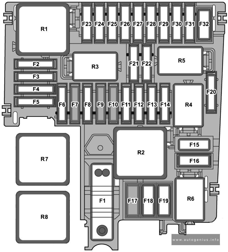
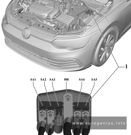
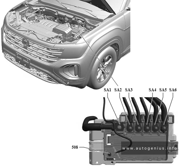
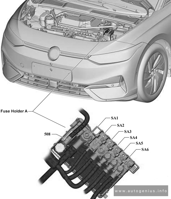
High Power Fuses (Fuse holder A -SA-)
Fuse Box Location and Diagram
Volkswagen Golf (MK8; 2020 – 2024) – fuse and relay box location – engine compartment (fuse holder A -SA-)
№
Amps
Function / component
SA1
150 A
Fuse holder B
SA2
50 A
Radiator fan
SA3
–
–
508
Battery
SA4
125 A
Fuse holder C
SA5
125 A
Fuse holder C
WARNING: Terminal and harness assignments for individual connectors will vary depending on vehicle equipment level, model, and market.
This article provides fuse box diagrams for the 2023 and 2024 Volkswagen Atlas, along with details on the location of the fuse panels within the vehicle. You’ll also find information on the fuse and relay assignments (fuse layout).
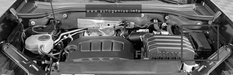
Passenger Compartment Fuse Box
Fuse Box Location
The interior fuse block is located in instrument panel.
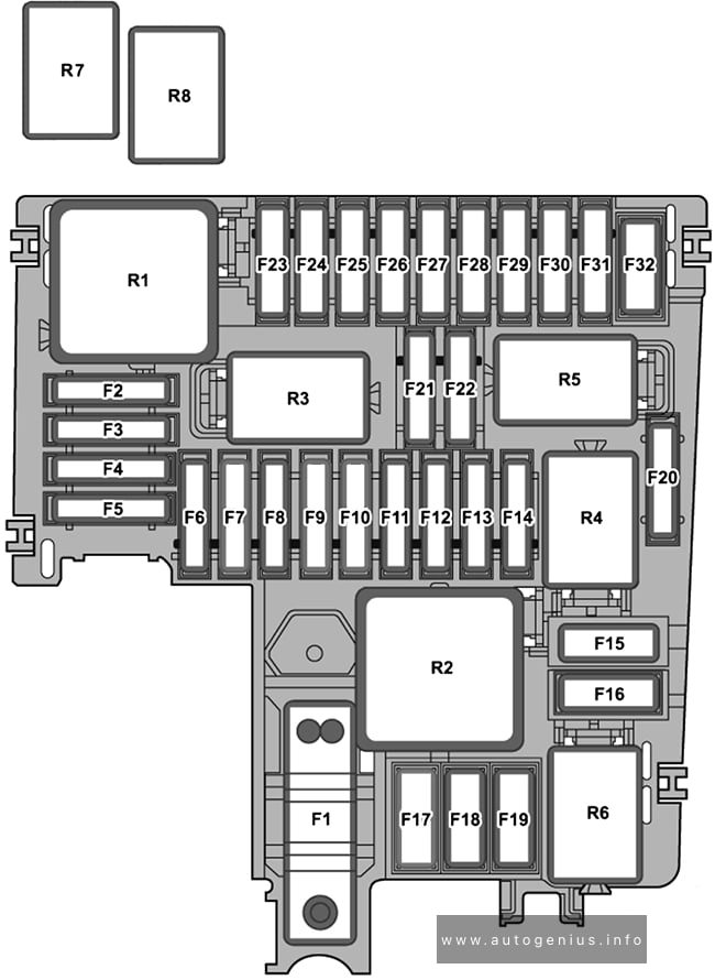
Assignment of the fuses in the passenger compartment (instrument panel)
№
A
Function / Component
F1
–
–
F2
30A
Rear fresh air blower control module
F3
25A
Towing Recognition Control Module
F4
–
–
F5
25A
Parking Lock Actuator
F6
30A
Vehicle Electrical System Control Module
F7
30A
Heater and A/C Controls
F8
20A
Sunroof Control Module
F9
30A
Driver Door Control Module
Left Rear Door Control Module
F10
–
–
F11
15A
Towing Recognition Control Module
F12
40A
Vehicle Electrical System Control Module
F13
40A
Vehicle Electrical System Control Module
F14
40A
Digital Sound System Control Module
F15
–
–
F16
7.5A
Airbag Control Module
F17
–
–
F18
7.5A
Access/Start System Interface
Burglary Protection Control Module 2
Burglary Protection Control Module 3
Burglary Protection Control Module 4
Burglary Protection Control Module 5
Electronic Steering Column Lock Control Module
F19
7.5A
Instrument Cluster
Control Module for Emergency Call Module and Communication Unit
F20
7.5A/15A
Storage Compartment with Cell Phone Interface
USB Connection 1
USB Charging Socket 1
USB Charging Socket 2
Third Row Seat Left USB Charging Socket
F21
7.5A
Lane Change Assistance Control Module
Lane Change Assistance Control Module 2
Rear Lid Opener Control Module
Peripheral Camera Control Module
Rear Lid Handle
F22
–
–
F23
–
–
F24
15A
All Wheel Drive Control Module
F25
–
–
F26
30A
‘front Passenger Door Control Module
Right Rear Door Control Module
F27
–
–
F28
–
–
F29
15A
Towing Recognition Control Module
F30
30A
Information Electronics Control Module 1
F31
25A
Towing Recognition Control Module
F32
25A
Rear A/C Display Control Head
F33
–
–
F34
30A
Converter with Socket, 12V-230V
F35
40A
Vehicle Electrical System Control Module
F36
40A
Fresh Air Blower Control Module
F37
30A
Rear Lid Control Module
F38
–
–
F39
–
–
F40
7.5A
Alarm Horn
F41
–
–
F42
7.5A
Selector mechanism
Selector Lever Transmission Range Display
F43
10A
Vehicle Interior Temperature Sensor
Heater and A/C Controls
Tire Pressure Monitoring Control Module
Rear A/C Display Control Head
Rear Window Defogger Relay
F44
7.5A
Parking brake button
Diagnostic Connection
Front Roof Module
Anti-Theft Alarm System Sensor
Illumination Control Head
Switch Module in Instrument Panel, Center
Cornering Lamp and Headlamp Range Control Module
Rain/Light Recognition Sensor
F45
7.5A
Steering Column Electronics Control Module
F46
7.5A
Windshield Projection Head Up Display Control Module
Front Information Display Control Head
F47
–
F48
10A/7.5A
USB Charging Socket 1
USB Charging Socket 2
Third Row Seat Left USB Charging Socket
USB Charging Socket in Headliner
F49
–
–
F50
–
–
F51
–
–
F52
20A
12 V Socket
F53
–
–
F54
–
–
F55
–
–
F56
–
–
F57
–
–
F58
7.5A
Driver Assistance Systems Front Camera
Parking Aid Control Module
Control Module for Adaptive Cruise Control
F59
7.5A
Structure-Borne Sound Control Module
Automatic Dimming Interior Rearview Mirror
Air Quality Sensor
Refrigerant Circuit Pressure Sensor
Sockets Relay
F60
7.5A
Diagnostic Connection
F61
7.5A
Starter Relay 1
Starter Relay 2
F62
–
–
F63
–
–
F64
7.5A
Passenger Occupant Detection System Control Module
Driver Seat Adjustment Control Module (Driver memory seat)
Driver Seat Lumbar Support Adjustment Switch (For vehicles with seat adjustment)
Left Front Seat Backrest Fan 1 (For vehicles with seat ventilation)
Left Front Seat Cushion Fan 1 (For vehicles with seat ventilation)
B
15A
Right Front Seat Adjustment Control Head (Driver memory seat)
Right Front Seat Backrest Fan 1 (For vehicles with seat ventilation)
Right Front Seat Cushion Fan 1 (For vehicles with seat ventilation)
C
30A
Electric Trailer Brake Position Sensor (For vehicles with trailer hitch)
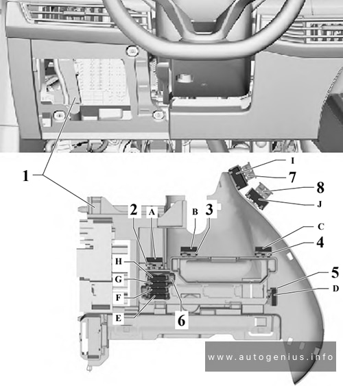
The Volkswagen ID.7, a battery-electric executive liftback, has been available since 2023. This article provides fuse box diagrams for the 2023 and 2024 Volkswagen ID.7 models, along with details on the fuse panel locations within the vehicle and the specific functions of each fuse and relay (fuse layout).
Passenger Compartment Fuse Box
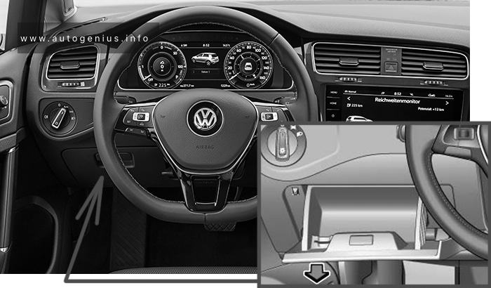
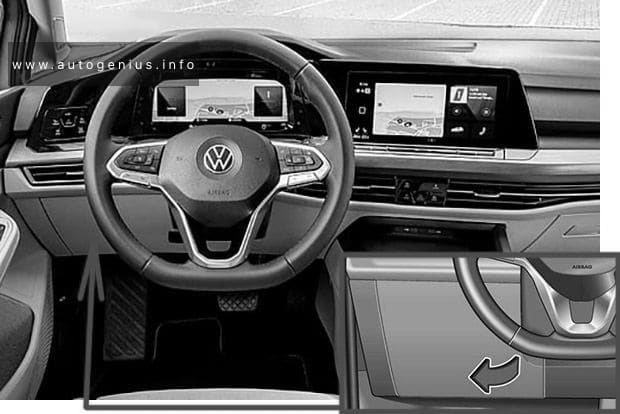
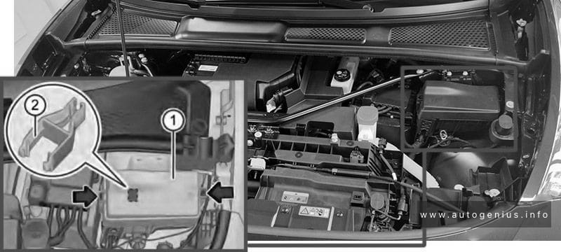
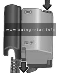
Fuse box location
Left-hand drive vehicle: Reach behind the cover and pull off in the direction of the arrow.
Assignment of the fuses in the instrument panel fuse box
№
Amps
Function / component
F1
–
–
F2
15A
Airbag control unit
F3
25A
Trailer detector control unit
F4
7.5A
Front camera for driver assist systems
F5
25A
Onboard supply control unit
F6
30A
Onboard supply control unit
F7
30A
Heater and air conditioning system control unit
F8
10A
Control unit 1 for electrically variable glass
Roof system control unit
F9
30A
Driver door control unit (LHD)
Front passenger door control unit (RHD)
Rear driver side door control unit (LHD)
Rear passenger side door control unit (RHD)
F10
5A
Left tail light cluster
Centre tail light cluster
F11
15A
Trailer detector control unit
F12
–
–
F13
40A
Onboard supply control unit
F14
40A
Digital sound package control unit
F15
–
–
F16
–
–
F17
5A
Parking aid control unit
Lane change assist control unit
Lane change assist control unit 2
F18
5A
Entry and start authorisation control unit
Control unit for electronic steering column lock
Rear lid power opening control unit
Control unit 2 for break-in protection
Control unit 3 for break-in protection
Control unit 4 for break-in protection
Control unit 5 for break-in protection
F19
5A
Navigation system interface
Control unit with display unit for driver information system
F20
7.5A
Charging unit 1 for mobile devices
Aerial amplifier for mobile telephone
USB connection 1
F21
7.5A
Control unit for overhead view camera
F22
5A
Engine/motor control unit
F23
5A
Internet access control unit
F24
5A
Right tail light cluster
Centre tail light cluster
F25
25A
Front left seat belt
F26
30A
Driver door control unit (RHD)
Front passenger door control unit (LHD)
Rear driver side door control unit (RHD)
Rear passenger side door control unit (LHD)
F27
25A
Front right seat belt
F28
10A
Battery regulation control unit
Maintenance connector for high-voltage system
Cable coil for emergency services cut-out connection
F29
15A
Trailer detector control unit
F30
25A
Control unit 1 for information electronics
F31
25A
Trailer detector control unit
F32
25A
Onboard supply control unit
F33
–
–
F34
15A
Heater and air conditioning system control unit
F35
40A
Operating and display unit for rear air conditioning system
F36
–
–
F37
30A
Rear lid control unit
F38
5A
Valve block 1 in driver seat
Valve block 2 in driver seat
Valve block 1 in front passenger seat
Valve block 2 in front passenger seat
F39
10A
Steering column electronics control unit
F40
7.5A
Alarm horn
F41
5A
Data bus diagnostic interface
F42
–
–
F43
1A
Operating and display unit for rear air conditioning system
Sensor for interior carbon dioxide concentration
Vehicle interior temperature sensor
Heated rear window relay
F44
7.5A
Hazard warning light switch
Rain and light sensor
Anti-theft alarm sensor
Centre switch module in dash panei
Operating unit for window regulator in driver door
Operating unit for lighting
Dynamic light strip 3 for information
Diagnostic connection
Front roof module
F45
5A
Steering column electronics control unit
F46
7.5A
Display unit for front information display and operating unit control unit
Control unit for Head-up Display
F47
7.5A
Electronically controlled damping control unit
F48
–
–
F49
–
–
F50
–
–
F51
–
–
F52
15A
12 V Socket 3
F53
–
–
F54
–
–
F55
–
–
F56
–
–
F57
–
–
F58
7.5A
Front right seat backrest fan 1
Front right seat cushion fan 1
Front right seat depth adjustment fan
F59
7.5A
Relay for power sockets
Automatic anti-dazzle interior mirror
F60
10A
Diagnostic connection
F61
5A
Power and control electronics for electric drive
F62
–
–
F63
7.5A
Front left seat backrest fan 1
Front left seat cushion fan 1
Front left seat depth adjustment fan
F64
–
–
F65
–
–
F66
–
–
F67
25A
Frequency modulation (FM) frequency filter in positive wire
A
Driver seat adjustment thermal fuse 1
B
Front passenger seat adjustment thermal fuse 1
R1
Power sockets relay
R2
Terminal 15 voltage supply relay
R3
Heated rear window relay
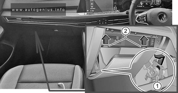
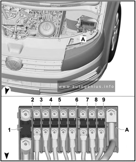
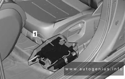
Front Compartment Fuse Box
Fuse box location
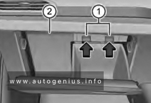
Press the locking button in the direction of the arrow (arrows) in order to unlock the cover of the fuse box.
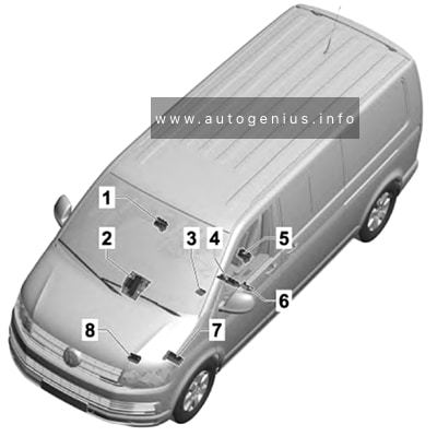
This article focuses on the sixth-generation Volkswagen Transporter (T6), manufactured from 2015 to 2019. It includes fuse box diagrams for Volkswagen Transporter T6 models from 2016 to 2019, provides details on the location of the fuse panels within the vehicle, and explains the function and layout of each fuse and relay.
Battery isolation relay
Second battery charging circuit relay
Fuses in fuse holder H: #25, 27
Left sliding door control unit
Right sliding door control unit
4
70 A
Positive connection (30) in engine compartment wiring harness
5
60 A / 80 A
ABS control unit
6
100 A
Heated windscreen relay
Automatic glow period control unit
7
100 A
Radiator fan control unit
8
50 A / 100 A
Positive connection 1 (30) in interior wiring harness
Positive connection 2 (30) in interior wiring harness
Positive connection 3 (30), in main wiring harness
Relay for reducing agent metering system (diesel Euro 6)
Reducing agent tank (diesel Euro 6)
Delivery unit for reducing agent metering system (diesel Euro 6)
14
5 A
Fuel pump relay (diesel)
Electric fuel pump 2 relay (diesel Euro 5)
15
10 A
Reversing light switch
16
5 A
Brake light switch
17
5 A
TCS and ESP button
Tyre Pressure Loss Indicator button
Hill descent control button
ABS control unit
18
5 A
Power steering control unit
19
5 A
Clutch pedal switch
Clutch position sender
Air mass meter (diesel)
20
5 A
Engine/motor control unit
Air mass meter (petrol)
21
–
not assigned
22
–
not assigned
23
10 A
Relay for reducing agent metering system
24
5 A
Selector lever
Mechatronic unit for dual clutch gearbox
25
20 A
Actuators 1-8 for camshaft adjustment
26
30 A
Heated windscreen
27
10 A
Continued coolant circulation pump (diesel Euro 5)
Charge air cooling pump (diesel Euro 6)
Pump for exhaust gas recirculation cooler (diesel Euro 6)
28
15 A
Control unit for sensor electronics (diesel Euro 6)
Particulate sensor (diesel Euro 6)
Control unit for NOx sender (diesel Euro 6)
NOx sender (diesel Euro 6)
29
15 A
Valve for oil pressure control (diesel Euro 6)
Coolant valve for cylinder head (diesel Euro 6)
Auxiliary pump for heating (diesel Euro 6)
Fuel shut-off valve switch-off relay (petrol)
Fuel pressure regulating valve (petrol)
30
20 A
Fuel pump relay (diesel)
Fuel system pressurisation pump (diesel)
Electric fuel pump 2 relay (diesel Euro 5)
Supplementary fuel pump (diesel Euro 5)
Fuel pump control unit (petrol)
Fuel system pressurisation pump (petrol)
31
15 A
Lambda probe
Lambda probe heater
Lambda probe after catalytic converter (petrol)
Lambda probe 1 heater after catalytic converter (petrol)
32
30 A
Engine/motor control unit
Ignition coils 1-4 with output stage (petrol)
33
5 A
Automatic glow period control unit (diesel)
Additional coolant pump relay (petrol, diesel Euro 5)
Fuel shut-off valve switch-off relay (petrol)
Coolant pump relay (petrol)
Continued coolant circulation pump (petrol)
34
5 A
Onboard supply control unit
35
5 A
Battery monitor control unit
36
30 A
Starter inhibitor relay
Starter
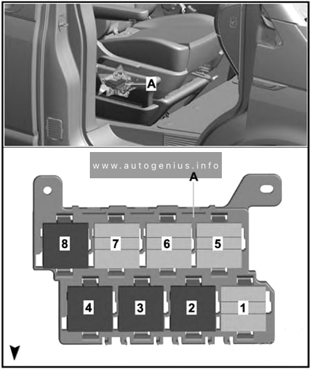
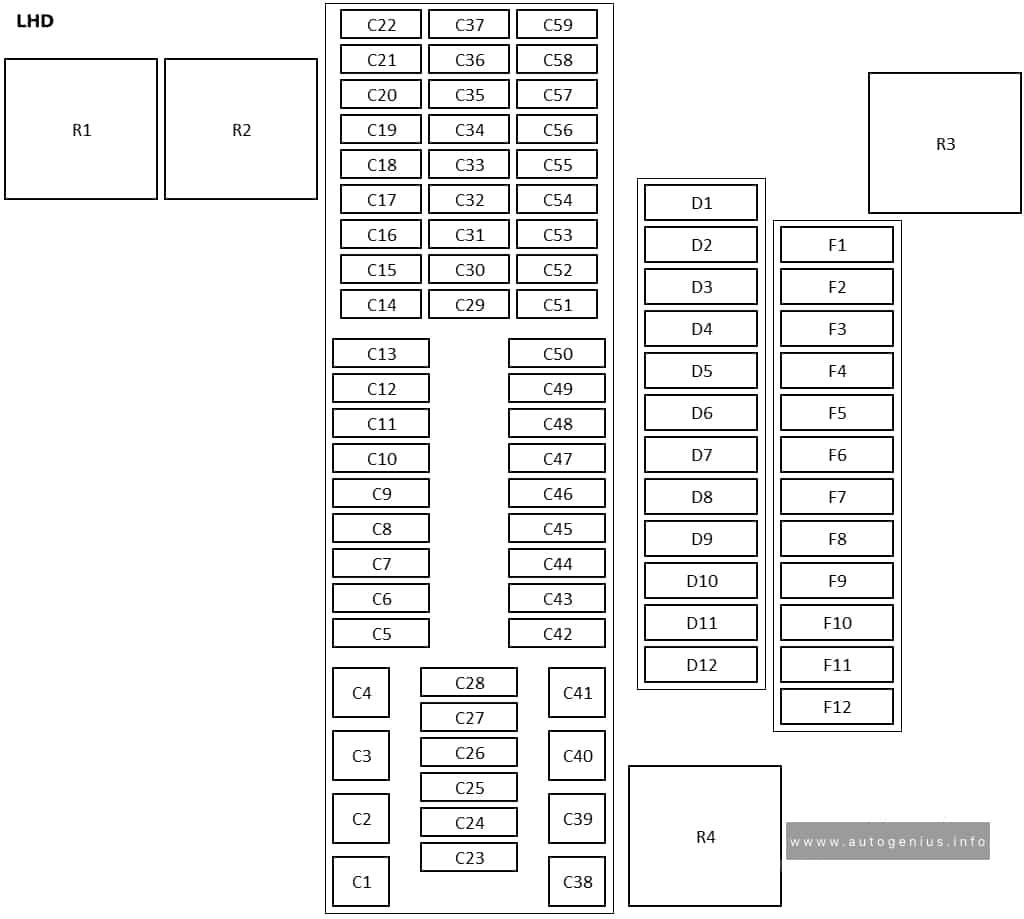
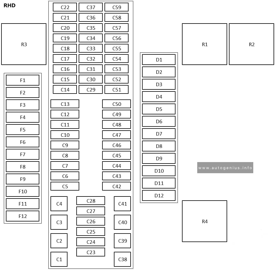
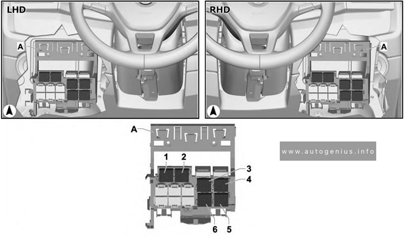
Fuse holders C -SC-, D -SD- and F -SF-
Fuse Box Location
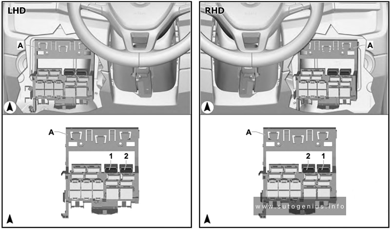
xVolkswagen Transporter (T6; 2016 – 2019) – fuse box location – passenger compartment (fuse holders C -SC-, D -SD- and F -SF-)
Grasp into the recess (arrow), and carefully open the cover;
Carefully pull the cover out of the mountings, and remove it.
Left-hand drive
xVolkswagen Transporter (T6; 2016 – 2019) – fuse box location – passenger compartment (fuse holders C -SC-, D -SD- and F -SF-) – left-hand drive
Right-hand drive
xVolkswagen Transporter (T6; 2016 – 2019) – fuse box location – passenger compartment (fuse holders C -SC-, D -SD- and F -SF-) – right-hand drive
Fuse Box Diagram
Left-hand drive
xVolkswagen Transporter (T6; 2016 – 2019) – fuse box diagram – passenger compartment (fuse holders C -SC-, D -SD- and F -SF-) – LHD
Right-hand drive
xVolkswagen Transporter (T6; 2016 – 2019) – fuse box diagram – passenger compartment (fuse holders C -SC-, D -SD- and F -SF-) – RHD
Assignment of the fuses and relays in the instrument panel fuse box (Fuse holders C, D and F)
№
Amps
Function/component
C1
40 A
Sender for front Bitron blower regulation
Fresh air blower
Auxiliary coolant heater relay
Fresh air blower switch
Air conditioning system control unit
C2
60 A
X-contact relief relay
Positive connection (X), in interior wiring harness
Fresh air and air recirculation flap switch
Rear fresh air blower switch
Fresh air blower isolation relay
C25
10 A
Rear window wiper motor
Rear left wing door window wiper motor
Rear right wing door window wiper motor
Left washer jet heater element
Right washer jet heater element
C26
5 A
Terminal 75 voltage supply relay 1
Onboard supply control unit
Interface for external use 6-pin connector
C26
15 A
Interface for external use 10-pin connector
C27
25 A
Heated front seats control unit
C28
5 A
Auxiliary coolant heater relay
C29
10 A
Airbag control unit
Warning lamp for airbag deactivated on front passenger side
C30
10 A
Mirror adjustment switch
Headlight range control regulator
Accident data recorder button
High-pressure sender
Air quality sensor
Oil level and oil temperature sender
Trailer detector control unit
Parking aid control unit
Headlight range control unit
Accident data memory
Front left headlight
Front right headlight
4-pin connector
10-pin connector
Diagnostic connection
Left headlight range control motor
Right headlight range control motor
Coolant shut-off valve relay
Climatronic coolant shut-off valve
Voltage supply relay 2
Parking aid control unit
C31
–
not assigned
C32
7.5 A
Light switch
Operating and display unit for camping equipment
Accident data recorder button
Start/Stop operation button
Tachograph
Steering angle sender
Electronically controlled damping control unit
Multifunction steering wheel control unit
Onboard supply control unit
Accident data memory
Main beam assist control unit
Dash panel insert
Automatic anti-dazzle interior mirror
Headlight dipper and flasher switch
Onboard supply control unit
C33
10 A
Rear differential lock switch
Vacuum switch for rear differential lock
All-wheel drive control unit
Differential lock control unit
Differential lock valve 1
Differential lock valve 2
C34
5 A
Operating and display unit for camping equipment
Internet access control unit
10-pin connector
Interface for external use 10-pin connector
C35
10 A
10-pin connector
12-pin connector
C35
15 A
Taximeter
Mirror taximeter
Taxi alarm remote control, control unit
C36
15 A
Intermittent wiper switch
Rear wiper switch
Washer pump switch (automatic wash/wipe and headlight washer system)
Onboard supply control unit
Washer pump
Rear window wiper motor
Windscreen and rear window washer pump
Rear left wing door window wiper motor
Rear right wing door window wiper motor
C37
5 A
Cruise control system switch
Cruise control system (CCS) SET button
Adaptive cruise control unit
Lane change assist control unit
Lane change assist control unit 2
C38
40 A
Ignition/starter switch
C39
20 A
Ignition/starter switch
C40
20 A
12 V socket 6
C40
30 A
Auxiliary heater relay
Fresh air blower series resistor with overheating fuse
C41
30 A
Onboard supply control unit
C42
25 A / 30 A
Fresh air blower isolation relay
Rear fresh air blower switch
C42
30 A
Rear blower regulation sender
Rear fresh air blower
C43
30 A
Control unit for reducing agent heater
C44
15 A
Rear lid control unit
C44
20 A
Alarm horn
Onboard supply control unit
Rear lid control unit
Left sliding door control unit
Right sliding door control unit
C45
30 A
Amplifier
C46
20 A
Auxiliary heater control unit
C47
25 A
Onboard supply control unit
C48
25 A
Sliding sunroof adjustment control unit
C49
15 A
Cigarette lighter
C50
25 A
Headlight washer system relay
Headlight washer system pump
C51
5 A
Steering angle sender
C52
5 A
Interior monitor send and receive module 1
Interior monitor send and receive module 2
C53
5 A
Rain and light sensor
C54
7.5 A
Operating and display unit for camping equipment
Roof display unit
Remote control receiver for auxiliary heater
Remote control receiver for auxiliary coolant heater
Residual heat relay
Circulation pump
C55
5 A
Operating and display unit for camping equipment
Onboard supply control unit
Roof hydraulics control unit
10-pin connector
Interface for external use 10-pin connector
C56
5 A
Starter inhibitor relay
Engine/motor control unit
Interfacefor external use 10-pin connector
Interface for external use 10-pin connector
C57
5 A
Operating and display unit for rear air conditioning system
C58
10 A
Tachograph
C59
5 A
Taximeter
Mirror taximeter
C59
10 A
Red cross light switch
Red cross light bulb
C59
10 A
Rotating light switch
Rotating light relay
Rotating light motor
D1
5 A
Two-way radio button
Front interior light (door contact) button
Ignition bypass button
Button for daytime running light switch-off
D1
5 A
Voltage supply relay 1
Voltage supply relay 2
Parking aid control unit
D1
15 A
Interior light switch (taxi)
Taximeter
Taxi alarm remote control, control unit
Two-way radio
D1
20 A
All-wheel drive control unit
D2
30 A
Special vehicle control unit
D3
15 A
Onboard charging unit
Internet access control unit
D3
15 A
Alarm horn relay
Treble horn
D3
30 A
Rear lid power opening control unit
D4
10 A
Interior light relay
Switch and instrument illumination regulator
D4
15 A
Alarm system relay 1
Onboard supply control unit
Front left headlight
D5
15 A
Alarm system relay 1
Onboard supply control unit
Front right headlight
D5
15 A
Electronically controlled damping control unit
D6
15 A
Interface for external use 10-pin connector
D6
25 A
10-pin connector
D7
5 A
Interface for external use 10-pin connector
D7
5 A
6-pin connector
D7
5 A
Interior light switch (taxi)
Taxi sign switch
D8
5 A
Accident data memory
D8
5 A
Accident data memory
6-pin connector
D8
15 A
Interface for external use 10-pin connector
D9
10 A
Relay 1 for ignition bypass
Relay 2 for ignition bypass
D9
25 A
Interface for external use 6-pin connector
D10
5 A
Interface for external use 10-pin connector
10-pin connector
D11
10 A
Accident data memory
D11
15 A
Accident data memory
10-pin connector
D11
15 A
Interface for external use 10-pin connector
D11
15 A
Accident data memory
Interface for external use 10-pin connector
D12
3 A
10-pin connector
Interface for external use 10-pin connector
F1
20 A
All-wheel drive control unit
F2
5 A / 10 A
Interior light relay
Switch and instrument illumination regulator
F3
30 A
Driver seat adjustment control unit
Switch module for front passenger seat
Front passenger seat longitudinal adjustment motor
Front passenger seat front height adjustment motor
Front passenger seat rear height adjustment motor
Front passenger seat backrest adjustment motor
F4
5 A
Emergency call module control unit and communication unit
F5
15 A
Electronically controlled damping control unit
F6
30 A
Driver seat adjustment control unit
Switch module for front passenger seat
Front passenger seat longitudinal adjustment motor
Front passenger seat front height adjustment motor
Front passenger seat rear height adjustment motor
Front passenger seat backrest adjustment motor
F7
5 A
Accident data memory
F8
–
not assigned
F9
5 A
Diagnosis wire relay
F9
5 A
Voltage supply relay 1
Voltage supply relay 2
Parking aid control unit
Right interior light
Rear right interior light
Kitchenette light 1
Kitchenette light 3
1-7*
Fuse 2 -S132-
15 A
12 V socket
1-7*
Fuse 3 -S133-
15 A
12 V socket 5
Kitchenette light 2
Front left reading light
4.1
Fuse 13 in fuse holder H -SH13-
7.5 A
Climatronic control unit
4.1
Fuse 13 in fuse holder H -SH13-
30 A
Auxiliary heater relay
Fresh air blower series resistor with overheating fuse
4.1
Fuse 13 in fuse holder H -SH13-
30 A
Auxiliary heater relay
Fresh air blower series resistor with overheating fuse
4.2
Fuse 14 in fuse holder H -SH14-
–
not assigned
4.3
Fuse 15 in fuse holder H -SH15-
30 A
Trailer voltage supply relay
Trailer socket
5.1
Fuse 22 in fuse holder H -SH22-
–
not assigned
5.2
Fuse 23 in fuse holder H -SH23-
–
not assigned
5.3
Fuse 24 in fuse holder H -SH24-
–
not assigned
6.1
Fuse 16 in fuse holder H -SH16-
30 A
Onboard charging unit
Light control relay
Kitchenette light 4
6.2
Fuse 17 in fuse holder H -SH17-
30 A
Roof hydraulics control unit
6.3
Fuse 18 in fuse holder H -SH18-
10 A
Rear right reading light
Right interior light
Rear right interior light
Kitchenette light 1
Kitchenette light 2
Kitchenette light 3
7.1
Fuse 19 in fuse holder H -SH19-
10 A
Refrigerator box
7.2
Fuse 20 in fuse holder H -SH20-
5 A
Water pump switch for shower
Water pump switch
Coolant pump
7.3
Fuse 21 in fuse holder H -SH21-
5 A
Operating and display unit for camping equipment
8.1
Fuse 1 in fuse holder H -SH1-
15 A
12 V socket 2
8.2
Fuse 2 in fuse holder H -SH2-
15 A
Onboard charging unit
Map reading light bulb
12 V socket
12 V socket 3
8.3
Fuse 3 in fuse holder H -SH3-
10 A
Switch-over relay 1 for roof ventilator
Switch for roof ventilator to ventilate load area
Switch for roof ventilator to extract air from load area
8.3
Fuse 3 in fuse holder H -SH3-
15 A
12 V socket 4
8.4
Fuse 4 in fuse holder H -SH4-
15 A
Trailer detector control unit
8.5
Fuse 5 in fuse holder H -SH5-
20 A
Trailer detector control unit
8.6
Fuse 6 in fuse holder H -SH6-
20 A
Trailer detector control unit
8.7
Fuse 7 in fuse holder H -SH7-
15 A
End position button for cupboard light
Cupboard light
Reading light relay
Left luggage compartment light
Rear lid light
Interior light
Front left reading light
Front right reading light
Rear lid light 2
Kitchen background lighting
8.7
Fuse 7 in fuse holder H -SH7-
10 A
10-pin connector
8.8
Fuse 8 in fuse holder H -SH8-
–
not assigned
8.9
Fuse 9 in fuse holder H -SH9-
5 A
Electric torch
8.10
Fuse 10 in fuse holder H -SH10-
15 A
12 V socket
8.10
Fuse 10 in fuse holder H -SH10-
30 A
DC/AC converter with socket, 12 V – 230 V
DC/AC converter with socket, 12 V -115 V
8.11
Fuse 11 in fuse holder H -SH11-
20 A / 25 A
Auxiliary heater control unit
8.12
Fuse 12 in fuse holder H -SH12-
15 A
Driver seat lumbar support adjustment switch
Front passenger seat lumbar support adjustment switch
9-15*
Fuse 25 in fuse holder H -SH25-
40 A
Right sliding door control unit
9-15*
Fuse 26 in fuse holder H -SH26-
80 A
Second battery
9-15*
Fuse 27 in fuse holder H -SH27-
40 A
Left sliding door control unit
9-15*
Fuse 28 in fuse holder H -SH28-
30 A
Onboard charging unit
9-15*
Fuse 29 in fuse holder H -SH29-
40 A
Sender for front Bitron blower regulation
Fresh air blower
9-15*
Fuse 30 in fuse holder H -SH30-
40 A
Interface for external use 6-pin connector
R1
Switch-over relay 1 for roof ventilator
R2
Differential lock control unit
R3
Alarm system relay 1
R4
not assigned
R5
Trailer voltage supply relay
R6
Battery isolation relay
R7
Rotating light relay
Taxi alarm remote control, control unit
Terminal 75 voltage supply relay 1
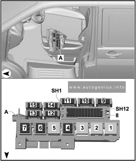
*1-7 and 9-15: fuse location depends on equipment level.
Year of production: 2010, 2011, 2012, 2013, 2014, 2015, 2016, 2017
This article covers the sixth-generation Volkswagen Jetta (A6, Typ 1B), produced from 2010 to 2017. It provides fuse box diagrams for the 2010, 2011, 2012, 2013, 2014, 2015, 2016, and 2017 models, details the locations of the fuse panels inside the vehicle, and explains the function of each fuse (fuse layout) and relay.
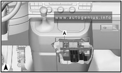
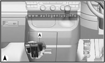
Passenger Compartment Fuse Box
Fuse Box Location
The fuse box is located behind the cover on the driver’s side. Pull the lower part of the cover in the direction of the arrow and remove the cover from the bottom. On the inside of the cover there are plastic tweezers for removing and inserting fuses.
Volkswagen Jetta (A6; 2010 – 2017) – fuse and relay diagram – passenger compartment (holder C)
Assignment of the fuses in the instrument panel (holder C)
№
Amps
Function/Component
F1
10A
2014-2017: Left washer nozzle heater Right washer nozzle heater
F2
5A/7,5A
Electronic steering column lock control module
F3
10A
Instrument cluster control module
F4
2A/10A
2012-2017: Telephone Transceiver Compass magnetic field sensor (vehicles equipped with Start/Stop)
F5
7.5A
2012-2017: Left rear fog lamp bulb
F6
10A
Vehicle electrical system control module (T73a/66) (interior lamp, AW0 only) Rearview camera (2014-2017)
F7
5A
Fog lamp relay (AW0 only) Instrument panel and switch illumination dimmer switch (AW0 only) License plate lamp Vehicle electrical system control module (T52c/27), (AW1 only)
F8
7.5A
Windshield and headlamp washer pump switch (AW0 only) Windshield washer pump (AW0 only) Vehicle electrical system control module (T73b/61), (AW0 only)
F8
–
not used (AW1 only)
F9
5A/15A
Arbag control module Airbag Control Module Front passenger airbag “disabled” indicator lamp Passenger occupant detection system control module
F10
10A
Right steering column switch (T10ls/3) (AW0 only)
F11
10A
2012-2017: Left front headlamp (HID headlamp)
F12
10A
2012-2017: Right front headlamp (HID headlamp)
F13
5A
Automatic dimming interior rearview mirror Light recognition sensor Parking aid control module Ar quality sensor High pressure sensor Climatronic control module Tire pressure monitoring button ASR/ESP button Back-up lamp switch Start/Stop mode switch 28-pin connector (T28/10) Mirror adjusting switch Exterior rearview mirror heating switch AC compressor control module (T14hy/14) (Engine code CNLA) Cornering lamp and headlamp range control module
F14
10A
Left steering column switch (T16ls/1) (AW0 only) ABS control module T26/20 / T47/8 Light switch (T10h/4) (AW1 only) Arbag spiral spring/return spring with slip ring (T16k/14) Fuel pump control module Towing recognition control module (T12a/2) Voltage stabilizer Converter with socket, 12V-230V (T3wr/3) Data bus on board diagnostic interface (AW1 only) Instrument cluster control module Selector lever sensor system control module Tiptronic switch (T10s/9) Power steering control module (T6z/1) Oil level thermal sensor (T6z/4) Hybrid battery unit (T14ax/7) (Engine code CNLA) Electric drive power and control electronics (T28jx/56) (Engine code CNLA)
F15
10A
16-pin connector (diagnostic connection) Instrument panel and switch illumination dimmer switch Headlamp range control adjuster (AW1 only) Fresh air blower relay Mass airflow sensor Positive crankcase ventilation heating element – Structure borne sound control module Left front headlamp Left headlamp beam adjustment motor Right front headlamp Right headlamp beam adjustment motor Vehicle electrical system control module (T73a/44)
F16
10A
Auxiliary engine coolant pump relay Fuel pump control module Engine control module Electric drive button (Engine code CNLA)
F17
10A
2012-2017: Anti-theft alarm system horn (Running change) Anti-theft alarm system interior sensor (Running change) Anti-theft alarm system alarm (Running change)
F18
15A
Left front headlamp Left low beam headlamp bulb (vehicles with China equipment)
F19
15A
Right front headlamp Right low beam headlamp bulb (vehicles with China equipment)
F20
10A
Ignition/starter switch (T10/10) (AW0 only) Tiptronic switch Automatic transmission control module Selector lever sensor system control module Climatronic control module Auxiliary engine coolant heater radio frequency receiver
F21
15A/20A
2012-2017: Vehicle electrical system control module (T73a/73), (AW0 only) Dual tone horn relay (AW1 only) High tone horn (AW1 only) Low tone horn (AW1 only)
Heater/heat output switch Fresh air blower relay AC control module Fresh air blower switch
F34
15A
Left high beam headlamp bulb (AW0 only) Right high beam headlamp bulb (AW0 only) Instrument cluster control module (AW0 only)
F35
10A
Steering column electronics control module (AW1 only) Data bus on board diagnostic interface (AW1 only) Instrument cluster control module (2010-2011) Signal horn activation (2010-2012)
F36
25A
Vehicle electrical system control module (T73a/16) (AW0 only) (T52b/1) (AW1 only) Vehicle electrical system control module (T73a/61) (AW0 only) (Running change)
F37
15A
Left front headlamp Left daytime running lamp bulb
F38
15A
Right front headlamp Right daytime running lamp bulb
F39
20A
Low beam relay
F40
15A
Towing recognition control module (T12a/9)
F41
15A
Towing recognition control module (T12a/12)
F42
20A
Towing recognition control module (T12a/11)
F43
30A
Front passenger door control module
F44
25A/30A
Rear window defogger relay (AW1 only) Rear window defogger Vehicle electrical system control module (T73b/67) (AW0 only)
F45
30A
Driver door control module Front passenger door control module (vehicles with China equipment)
F46
30A
Left rear door control module Right rear door control module
F47
15A
Fuel pump control module Fuel pump relay Fuel primer relay
F48
20A
Vehicle electrical system control module
F49
40A
Fresh air blower Climatronic control module A/C control module
Engine control module Engine component power supply relay
F3
5A/10A
Coolant fan control module Relay for low heat output Relay for high heat output
F4
5A/10A/15A
Oxygen sensor heater Heater for oxygen sensor 1 after catalytic converter High temperature circuit coolant pump (Engine codes CNLA, CRJA) Low temperature circuit coolant pump
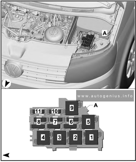
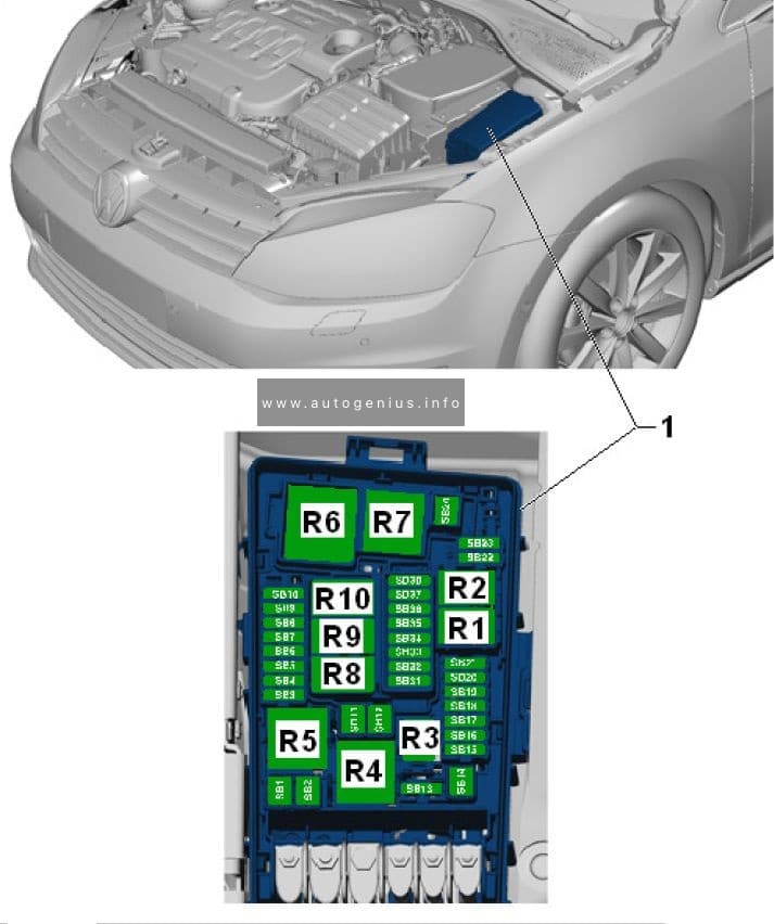
Volkswagen Golf VII (mk7; 2013 – 2020) – fuse and relay box diagram
Year of production: 2013, 2014, 2015, 2016, 2017, 2018, 2019, 2020
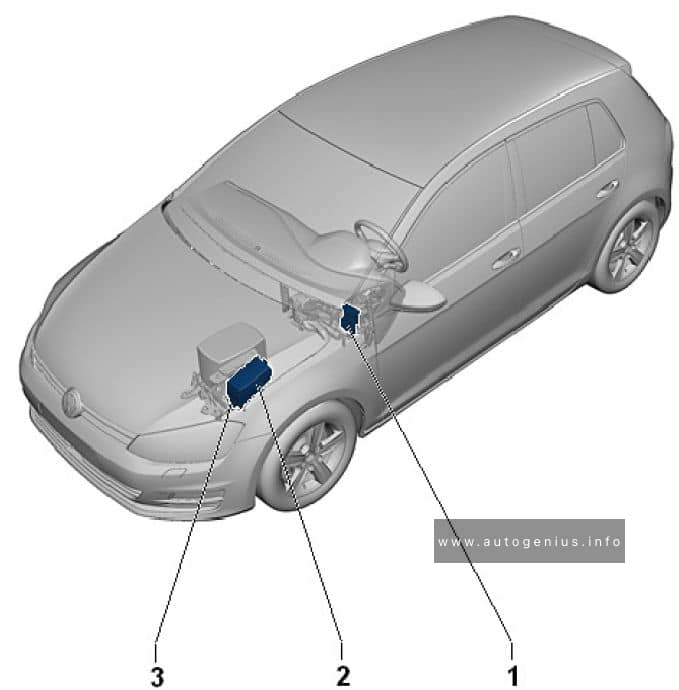
Overview of fuse holder
Volkswagen Golf VII (mk7; 2013 – 2020) – fuse and relay box location – overview of fuse holder
№
Description
1
Fuse panel C -SC-
2
Fuse panel B -SB-
3
Fuse panel A -SA-
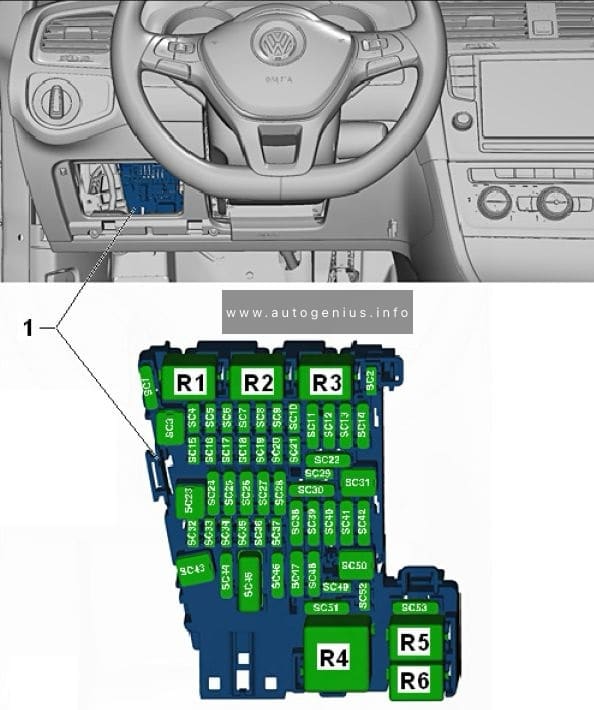
Passenger Compartment Fuse Box
Fuse Box Diagram (Fuse Panel C- SC)
Volkswagen Golf VII (mk7; 2013 – 2020) – fuse and relay box location – passenger compartment (fuse panel C -SC-)
Fuse assignment fuse panel C -SC-
№
Designation in Wiring Diagram
A
Component
Terminal
F1
—
—
—
—
F2
—
—
—
—
F3
—
—
—
—
F4
Fuse 4 on fuse panel C -SC4-
10
Vehicle electrical system control module -J519-,
Anti-theft alarm system
30
F5
Fuse 5 on fuse panel C -SC5-
5
Data bus on board diagnostic interface -J533-
30
F6
Fuse 6 on fuse panel C -SC6-
5
Anti-theft alarm system sensor -G578-
30
F7
Fuse 7 on fuse panel C -SC7-
10
Heater and A/C controls -EX21-
Heater control module -J65-
Climatronic control unit -J255-
A/C control module -J301-
Selector lever -E313-
Auxiliary engine coolant heater radio
frequency receiver -R149-
Rear window defogger relay -J9-
Electronic steering column lock control module
-J764-
30
F16
Fuse 16 on fuse panel C -SC16-
7,5
Mobile communication 2-way signal amplifier -J984-
Antenna amplifier 3 -R112-
Voltage converter for USB charge module -A5-
30
F17
Fuse 17 on fuse panel C -SC17-
5
Instrument cluster control module -J285-
Instrument cluster -KX2-
30
F18
Fuse 18 on fuse panel C -SC18-
7,5
Rearview camera -R189-
Rear lid unlock switch -E165-
30
F19
Fuse 19 on fuse panel C -SC19-
7,5
Access/start system interface -J965-
30
F20
—
—
—
—
F21
—
—
—
—
F22
—
—
—
—
F23
Fuse 23 on fuse panel C -SC23-
40
Vehicle electrical system control module -J519-
Right front headlamp -MX2-
30
F24
Fuse 24 on fuse panel C -SC24-
30
Power sunroof control module -J245-
30
F25
Fuse 25 on fuse panel C -SC25-
30
Driver door control module -J386- 1)
Left rear window regulator motor -V26- 1)
Front passenger door control module -J387- 2)
Right rear window regulator motor -V27- 2)
30
F26
Fuse 26 on fuse panel C -SC26-
20
Vehicle electrical system control module -J519-
Front heated seat
30
F27
Fuse 27 on fuse panel C -SC27-
30
Digital Sound System Control Module -J525-
30
F28
Fuse 28 on fuse panel C -SC28-
20
Towing recognition control module -J345-
30
F29
—
—
—
—
F30
Fuse 30 on fuse panel C -SC30-
25
Left front seat belt tensioner control module -J854-
30
F31
Fuse 31 on fuse panel C -SC31-
40
Vehicle electrical system control module -J519-
Left front headlamp -MX1-
30
F32
Fuse 32 on fuse panel C -SC32-
7,5
Driver assistance systems front camera -R242-
Distance regulation control module -J428-
Parking aid control module -J446-
Parallel parking assistance control module –
J791-
15
F33
Fuse 33 on fuse panel C -SC33-
5
Airbag control module -J234-
15
Front passenger airbag -disabled- indicator
lamp -K145-
Diagnostic connection -U31-
Headlamp range control and instrument
illumination regulator -EX14-
Automatic dimming interior rearview mirror -Y7
–
Cornering lamp and headlamp range control
module -J745-
Left headlamp beam adjustment motor -V48-
Right headlamp beam adjustment motor -V49-
15
F36
Fuse 36 on fuse panel C -SC36-
10
Right daytime running lamp and parking lamp
control module -J861-
15
F37
Fuse 37 on fuse panel C -SC37-
10
Left daytime running lamp and parking lamp
control module -J860-
15
F38
Fuse 38 on fuse panel C -SC38-
20
Towing recognition control module -J345-
30
F39
Fuse 39 on fuse panel C -SC39-
30
Front passenger door control module -J387-
Right rear window regulator motor -V27- 1)
Driver door control module -J386- 2)
Left rear window regulator motor -V26- 2)
30
F40
Fuse 40 on fuse panel C -SC40-
20
Cigarette lighter -U1-3)
12 V socket -U5-
12 V socket 2 -U18-
12 V socket 3 -U19-
15/30 4)
F41
Fuse 41 on fuse panel C -SC41-
10
Steering column electronics control module -J527-
30
F42
Fuse 42 on fuse panel C -SC42-
40
Vehicle electrical system control module -J519-
Central locking system
30
F43
Fuse 43 on fuse panel C -SC43-
30
Vehicle electrical system control module -J519-
30
F44
Fuse 44 on fuse panel C -SC44-
15
Towing recognition control module -J345-
30
F45
Fuse 45 on fuse panel C -SC45-
15
Driver seat lumbar support adjustment switch -E176-
Driver seat adjustment control head -E470-
Front passenger seat adjustment control head -E471-
Front passenger seat lumbar support adjustment switch -E177-
Fuel pressure regulator valve -N276-1)
Charge air cooling pump -V188-1)
Oil pressure regulation valve -N428-2)
Cooling circuit solenoid valve -N492-2)
Charge air cooling pump -V188-2)
Heater support pump -V488- 2)
87
10 2)
F8
Fuse 8 on fuse panel B -SB8-
10 1)
Oxygen sensor heater -Z19-
Oxygen sensor 1 before catalytic converter -GX10-
Heater for oxygen sensor 1 after catalytic converter -Z29-
Oxygen sensor 1 after catalytic converter -GX7-
Mass airflow sensor -G70-
87
F9
Fuse 9 on fuse panel B -SB9-
5 2)
Ignition coil 1 with power output stage -N70- 1)
Ignition coil 2 with power output stage -N127-1)
Ignition coil 3 with power output stage -N291-
1)
Ignition coil 4 with power output stage -N292-1)
Automatic glow time control module -J179- 2)
Early fuel evaporation heating element -N51- 2)
87
20 1)
F10
Fuse 10 on fuse panel B -SB10-
15 1)
Fuel pump control module -J538-
87
20 2)
F11
Fuse 11 on fuse panel B -SB11-
40
Auxiliary heater heating element -Z35-
87
F11
Fuse 11 on fuse panel B -SB11-
40
Auxiliary heater heating element -Z35-
87
F12
Fuse 12 on fuse panel B -SB12-
40
Auxiliary heater heating element -Z35-
87
F13
Fuse 13 on fuse panel B -SB13-
30
DSG transmission Mechatronic -J743-
30
F14
—
—
—
—
F15
Fuse 15 on fuse panel B -SB15-
15
Horn relay -J413-
30
F16
—
—
—
—
F17
Fuse 17 on fuse panel B -SB17-
7,5
Motronic engine control module power supply
relay -J271- 1)
Terminal 30 power supply relay -J317-2)
Engine control module -J623-
ABS control module -J104-
30
F18
Fuse 18 on fuse panel B -SB18-
5
Battery monitoring control module -J367-
Data bus on board diagnostic interface -J533-
3)
30
F19
Fuse 19 on fuse panel B -SB19-
30
Wiper motor control module -J400-
30
F20
Fuse 20 on fuse panel B -SB20-
20
Anti-theft alarm system horn -H8-
30
F21
—
—
—
—
F22
Fuse 22 on fuse panel B -SB22-
5
Engine control module -J623-
50
F23
Fuse 23 on fuse panel B -SB23-
30
Starter -B-
50
F24
Fuse 24 on fuse panel B -SB24-
40
Auxiliary heater heating element -Z35-
87
F25
—
—
—
—
F26
—
—
—
—
F27
—
—
—
—
F28
—
—
—
—
F29
—
—
—
—
F30
—
—
—
—
F31
—
—
—
—
F32
—
—
—
—
F33
—
—
—
—
F34
—
—
—
—
F35
—
—
—
—
F36
—
—
—
—
F37
Fuse 37 on fuse panel B -SB37-
20
Auxiliary heater control module -J364-
30
F38
—
—
—
—
1) Only for vehicles with gasoline engine
2) only for vehicles with a diesel engine
3) Only for vehicles without Stop/Start
Engine Compartment Fuse Box
Fuse Box Diagram (Fuse Panel A- SA)
Volkswagen Golf VII (mk7; 2013 – 2020) – fuse and relay box location – engine compartment (fuse panel A -SA-)
Fuse assignment fuse panel A -SA-
№
Designation in Wiring Diagram
A
Component
Terminal
J
Fuse 1 on fuse panel A -SA1-
100
Fuses Supply:
-SC4- …-SC14-
-SC30-
-SC31-
-SC38-
-SC39-
-SC41-
-SC42-
-SC53-
Front passenger power seat adjustment
circuit breaker 1 -S46-
Terminal 15 power supply relay -J329-
J160 – Circulation pump relay2)
J708 – Residual heat relay2)
R149 – Remote control receiver for auxiliary coolant heater2)
U18 – 12 V socket 21)
U20 – 12 V socket 41)
3
15
202)
U5 – 12 V socket
U19 – 12 V socket 3
4
20
J162 – Heater control unit
5
20
U18 – 12 V socket 22)
U19 – 12 V socket 42)
J807 – Relay for power sockets1)
6
15
J518 – Entry and start authorisation control unit3)
J708 – Residual heat relay1)
7
5
T16b – Diagnostic connection
J515 – Aerial selection control unit
G397 – Rain and light detector sensor
8
25
307)
V – Windscreen wiper motor
9
15
J519 – Onboard supply control unit (windscreen wiper pump)
10
25
307)
J388 – Rear left door control unit (window regulator)
11
15
J386 – Driver door control unit (central locking)
J388 – Rear left door control unit (central locking)
12
10
J519 – Onboard supply control unit (interior light)
13
–
Not assigned
14
25
307)
J386 – Driver door control unit (window regulator)
15
15
J393 – Convenience system central control unit (right tail light cluster)
16
20
J519 – Onboard supply control unit (fanfare)
17
30
J519 – Onboard supply control unit (left light)
18
20
257)
J39 – Headlight washer system relay
19
–
Not assigned
20
30
J519 – Onboard supply control unit (battery 1)
21
–
Not assigned
22
30
J647 – Axle differential lock control unit
J605 – Rear lid control unit
23
10
J647 – Axle differential lock control unit
24
5
J502 – Tyre pressure monitor control unit
25
15
J352 – Steering column and belt height adjustment control unit
26
10
F36 – Clutch pedal switch
J… – Engine control units
J234 – Airbag control unit
J285 – Control unit in dash panel insert
J519 – Onboard supply control unit
K145 – Front passenger side airbag deactivated warning lamp
N378 – Driver seat belt inertia reel magnet
N379 – Front passenger side seat inertia reel magnet
27
5
E183 – Interior monitoring switch
W11 – Rear left reading light
W12 – Rear right reading light
W14 – Front passenger side illuminated vanity mirror
W20 – Driver side illuminated vanity mirror
W51 – Rear lid light
28
–
Not assigned
29
–
Not assigned
30
–
Not assigned
31
–
Not assigned
32
–
Not assigned
33
15
J527 – Steering column electronics control unit
34
5
G273 – Interior monitoring sensor
G384 – Vehicle inclination sender
J285 – Control unit in dash panel insert2)
35
30
J519 – Onboard supply control unit
36
30
E470 – Driver seat adjustment operating unit
37
–
Not assigned
38
–
Not assigned
39
5A
J9 – Heated rear window relay
J32 – Air conditioning system relay
J329 – Terminal 15 voltage supply relay
J755 – Transport mode relay
J807 – Relay for power sockets1)
40
5
J285 – Control unit in dash panel insert
41
15
J518 – Entry and start authorisation control unit
42
30
J245 – Sliding sunroof adjustment control unit
43
–
Not assigned
44
30
E470 – Driver seat adjustment operating unit
J136 – Seat and steering column adjustment control unit with memory
J810 – Driver seat adjustment control unit
45
25
J786 – Heated rear seats control unit
46
–
Not assigned
47
10
J647 – Axle differential lock control unit
48
5
J769 – Lane change assist control unit
J770 – Lane change assist control unit 2
49
5
J236 – Servotronic control unit
50
10
G266 – Oil level and oil temperature sender
N79 – Crankcase breather heater element4)
51
5
T16b – Diagnostic connection
F321 – Parking brake contact switch
G238 – Air quality sensor
G550 – Sensor for automatic distance control
J755 – Transport mode relay
52
30
157)
V12 – Rear window wiper motor
53
5
E1 – Light switch
J527 – Steering column electronics control unit
J393 – Convenience system central control unit
54
10
E102 – Headlight range control regulator5)
J667 – Power output module for left headlight6)
V48 – Left headlight range control motor5)
V49 – Right headlight range control motor5)
55
15
J486 – Fresh air blower relay for 2nd speed
56
40
J32 – Air conditioning system relay
J309 – Solar cell isolation relay
J486 – Fresh air blower relay, 2nd speed
SB55 – Fuse 55 on fuse holder B
V305 – Motor for front Bitron blower regulation
57
40
V306 – Motor for rear Bitron blower regulation8)
J403 – Adaptive suspension compressor relay7)
1) Only one battery onboard supply
2) Only auxiliary battery and two battery onboard supply
3) Only V10 TDI
4) Only models with engine codes BHK, BHL
5) Only models with halogen headlights
6) Only models with cornering light
7) From November 2007
8) Up to November 2007
Fuse assignment in fuse box, right-side dash panel
Assignment of the fuses in the right-side of the dash panel.
No.
А
Function/component
1
15
202)
J345 – Trailer detector control unit
2
5
J446 – Parking aid control unit
3
15
J345 – Trailer detector control unit
4
5
J412 – Mobile telephone operating electronics control unit
5
15
252)
J345 – Trailer detector control unit
6
30
J104 – ABS control unit
7
5
J646 – Transfer box control unit
8
30
J519 – Onboard supply control unit (right light)
9
10
Individualisation
R190 – Satellite digital radio tuner1)
10
5
J772 – Reversing camera system control unit
R78 – TV tuner
11
20
J503 – Control unit with display for radio and navigation system
R – Radio
R – Preparation for radio and navigation system with TV (models for Japan)
12
30
R12 – Amplifier
13
–
Not assigned
14
15
J393 – Convenience system central control unit
15
25
303)
J389 – Rear right door control unit (window regulator)
16
10
53)
W3 – Luggage compartment light
17
–
Not assigned
18
30
J9 – Heated rear window relay
19
–
Not assigned
20
30
U13 – AC/DC converter with socket 12 V – 230 V
U27 – AC/DC converter with socket 12 V – 115 V1)
21
10
F266 – Bonnet contact switch
22
25
J774 – Heated front seats control unit
23
10
J255 – Climatronic control unit
24
30
E471 – Front passenger seat adjustment operating unit
J521 – Front passenger seat adjustment with memory control unit
25
5
E265 – Rear Climatronic operating and display unit
J301 – Air conditioning system control unit
26
–
Not assigned
27
15
J197 – Adaptive suspension control unit
28
–
Not assigned
29
10
53)
J217 – Automatic gearbox control unit
30
20
J714 – Power latching system relay
31
15
J393 – Convenience system central control unit
32
10
J387 – Front passenger door control unit (central locking)
J389 – Rear right door control unit (central locking)
33
15
Individualisation
34
25
303)
J387 – Front passenger side door control unit (window regulator)
35
30
E471 – Front passenger seat adjustment operating unit
36
5
J603 – Vehicle position recognition control unit
J702 – Roof display unit
37
–
Not assigned
38
10
J104 – ABS control unit
39
5
J410 – Heated windscreen relay for left side
J411 – Heated windscreen relay for right side
J745 – Cornering light and headlight range control unit
Individualisation
40
10
J646 – Transfer box control unit
41
10
J345 – Trailer detector control unit
42
5
E284 – Garage door operating unit
J530 – Garage door operation control unit
43
5
F41 – Reversing switch
44
5
E94 – Heated driver seat regulator
E95 – Heated front passenger seat regulator
E128 – Heated rear left seat switch with regulator
E129 – Heated rear right seat switch with regulator
E281 – Operating unit to regulate suspension height
Z20 – Left washer jet heater element
Z21 – Right washer jet heater element
45
–
Not assigned
46
–
Not assigned
47
10
J668 – Power output module for right headlight
48
10
J197 – Adaptive suspension control unit
49
5
Y7 – Automatic anti-dazzle interior mirror
50
5
E256 – TCS and ESP button
51
15
J217 – Automatic gearbox control unit
52
5
F125 – Multifunction switch
F189 – Tiptronic switch
N380 – Selector lever lock for position P solenoid
53
30
J411 – Heated windscreen relay for right side
54
30
J410 – Heated windscreen relay for left side
55
–
Not assigned
56
40
J104 – ABS control unit
57
40
J646 – Transfer box control unit
1) Only American markets
2) From May 2008
3) From November 2007
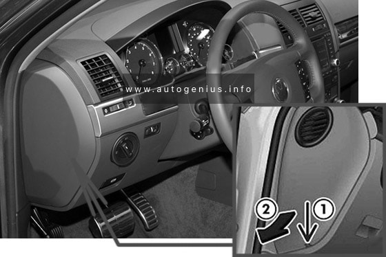
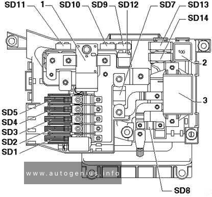
Fuses and relay position assignment in pre-fuse box, under driver seat
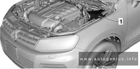
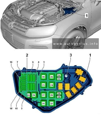
Fuse box diagram
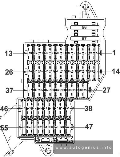
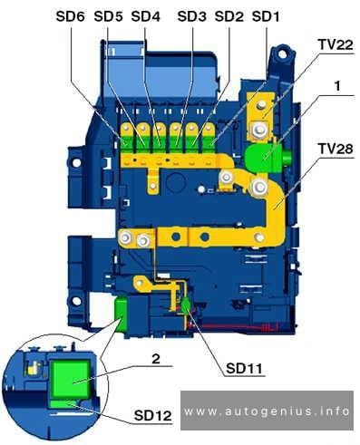
Volkswagen Touareg – fuse and relay box diagram – passenger compartment (pre-fuse, under driver seat)
Pre-fuse box (under driver seat).
No.
А
Function/component
SD1
150
Left fuse carrier
SD2
150
Right fuse carrier
SD3
60
Right fuse carrier
SD4
60
403)
J701 – Voltage supply relay 21)
V306 – Motor for rear Bitron blower regulation3)
SD5
60
403)
J329 – Terminal 15 voltage supply relay
SD6
–
Not assigned
SD7
250
J713 – Charger relay for second battery
SD8
1501)
602)
Left fuse carrier
J701 – Voltage supply relay 11)
SD9
5
J519 – Onboard supply control unit
SD10
10
53)
J519 – Onboard supply control unit1)
SD11
5
J519 – Onboard supply control unit1)
SD12
–
Not assigned
SD13
40
J403 – Adaptive suspension compressor relay
V306 – Motor for rear Bitron blower regulation1,3)
SD14
–
Not assigned
Relays
1
Battery master/isolator switch -E74-
2
Terminal 15 voltage supply relay -J329- (433)
3
Second battery charging circuit relay -J713-
1) Only V10 TDI
2) Only models with additional battery
3) From November 2007
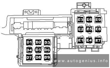
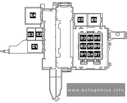
Relay locations for E-box on left under dash panel near centre console
Fuse box diagram
Volkswagen Touareg – fuse and relay box diagram – passenger compartment (e-box; left-side under dashpanel)
Relay panel E-Box 1 (on left under dash panel near center console).
No.
Function/component
D1
Servotronic control unit -J236- (476)
D2
Power latching system relay -J714- (404)
D3
Adaptive suspension compressor relay -J403- (373)
D4
Power sockets relay -J807- (404)
D5
Air conditioning system relay -J32- (100) / (370) optional installation
D6
Fresh air blower relay, 2nd speed -J486- (404), only manually operated air conditioning system
D7
Heated rear window relay -J9- (53)
D8
Circulation pump relay -J160- (404), only VR6 with auxiliary heater
D9
Alternator cut-in relay -J442- (53)
E1
Solar cells isolation relay -J309- (79)
E2
Not assigned
E3
Heated windscreen relay for left side -J410- (53)
E4
Not assigned
E5
Voltage supply relay 2 -J710- (432), only V10 TDI
E6
Not assigned
E7
Headlight washer system relay -J39- (53)
E8
Residual heat relay -J708- (404)
E9
Heated windscreen relay for right side -J411- (53)
Relay carrier on E-box on right under dash panel, near right a-pillar (only right-hand drive)
Fuse box diagram
Volkswagen Tourareg – fuse and relay box diagram – relay carrier on E-box on right-side under dash panel, near right a-pillar (only right-hand drive)
Relay panel E-box 2 (on right under dash panel, near right a-pillar)
No.
Function/component
D1
Servotronic control unit -J236- (476)
D2
Power latching system relay -J714- (404)
D3
Adaptive suspension compressor relay -J403- (373)
D4
Power sockets relay -J807- (404)
D5
Air conditioning system relay -J32- (100) / (370) optional installation
D6
Fresh air blower relay, 2nd speed -J486- (404), only manually operated air conditioning system
D7
Heated rear window relay -J9- (53)
D8
Circulation pump relay -J160- (404), only VR6 with auxiliary heater
D9
Alternator cut-in relay -J442- (53)
E1
Solar cells isolation relay -J309- (79)
E2
Residual heat relay -J708- (404)
E3
Heated windscreen relay for left side -J410- (53)
E4
Voltage supply relay 2 -J710- (432), only V10 TDI
E5
Heated windscreen relay for right side -J411- (53)
Volkswagen Touareg – fuse and relay box diagram – engine compartment relay & fuse box (2.5 l (R5) TDI engine)
Assignment of the fuses in the Engine compartment (2.5L (R5) TDI engine)
No.
A
Function/component
1
60
J293 – Radiator fan control unit
2
30
J671 – Radiator fan control unit 21)
3
–
Not assigned
4
–
Not assigned
5
–
Not assigned
6
–
Not assigned
7
–
Not assigned
8
–
Not assigned
9
30
J623 – Engine control unit
10
10
G65 – High-pressure sender
J17 – Fuel pump relay
J255 – Climatronic control unit
J293 – Radiator fan control unit
J301 – Air conditioning system control unit
J445 – Fuel cooling pump relay
J496 – Additional coolant pump relay
J671 – Radiator fan control unit 2
N75 – Charge pressure control solenoid valve
N79 – Crankcase breather heater element
N280 – Air conditioner compressor regulating valve
N345 – Exhaust gas recirculation cooler changeover valve
11
–
Not assigned
12
10
J179 – Automatic glow period control unit
J496 – Additional coolant pump relay
J248 – Diesel direct injection system control unit
J623 – Engine control unit
10
10
G65 – High-pressure sender
J17 – Fuel pump relay
J179 – Automatic glow period control unit
J255 – Climatronic control unit
J293 – Radiator fan control unit
J301 – Air conditioning system control unit
J338 – Throttle valve module3)
J442 – Alternator cut-in relay2)
J445 – Fuel cooling pump relay
J496 – Additional coolant pump relay
J671 – Radiator fan control unit 2
J724 – Turbocharger 1 control unit
J865 – Control unit for charge air cooler bypass3)
N18 – Exhaust gas recirculation valve
N280 – Air conditioner compressor regulating valve
N345 – Exhaust gas recirculation cooler changeover valve
N381 – Exhaust gas recirculation cooler changeover valve 23)
N428 – Valve block 2 in front passenger side rear seat3)
V157 – Intake manifold flap motor
V275 – Intake manifold flap 2 motor
V400 – Pump for exhaust gas recirculation cooler3)
G65 – High-pressure sender
J17 – Fuel pump relay
J293 – Radiator fan control unit
J671 – Radiator fan control unit 2
N345 – Exhaust gas recirculation cooler changeover valve
N381 – Exhaust gas recirculation cooler changeover valve 2
V336 – Metering pump for post-injection in particulate filter for cylinder bank 12)
V337 – Metering pump for post-injection in particulate filter for cylinder bank 22)
11
15
F265 – Map-controlled engine cooling system thermostat
J255 – Climatronic control unit
J724 – Turbocharger 1 control unit
J725 – Turbocharger 2 control unit
N280 – Air conditioner compressor regulating valve
V135 – Particulate filter additive pump2)
V157 – Intake manifold flap motor
V275 – Intake manifold flap 2 motor
V280 – Turbocharger 1 control motor
V281 – Turbocharger 2 control motor
12
5
J179 – Automatic glow period control unit
J445 – Fuel cooling pump relay
J496 – Additional coolant pump relay
J703 – Glow period control unit 2
Volkswagen Touarge – fuse and relay box diagram – engine compartment relay & fuse box (3.6 l (V6) FSI engine)
Assignment of the fuses in the Engine compartment (3.6L (V6) FSI engine)
No.
A
Function/component
1
60
J293 – Radiator fan control unit
2
301)
J671 – Radiator fan control unit 2
V7 – Radiator fan
3
–
Not assigned
4
–
Not assigned
5
–
Not assigned
6
–
Not assigned
7
20
N70 – Ignition coil 1 with output stage
N127 – Ignition coil 2 with output stage
N291 – Ignition coil 3 with output stage
8
20
N292 – Ignition coil 4 with output stage
N323 – Ignition coil 5 with output stage
N324 – Ignition coil 6 with output stage
9
30
J623 – Engine control unit
10
10
G65 – High-pressure sender
J293 – Radiator fan control unit
J496 – Additional coolant pump relay
J671 – Radiator fan control unit 21)
V144 – Fuel system diagnostic pump
11
10
J255 – Climatronic control unit
J301 – Air conditioning system control unit
J442 – Alternator cut-in relay2)
N280 – Air conditioner compressor regulating valve
12
10
N80 – Activated charcoal filter system solenoid valve 1
N205 – Inlet camshaft control valve 1
N316 – Intake manifold flap valve
N318 – Exhaust camshaft control valve 1
13
25
J538 – Fuel pump control unit
14
15
N276 – Fuel pressure regulating valve
15
10
J623 – Engine control unit
J271 – Motronic current supply relay
J670 – Motronic current supply relay 2
Volkswagen Touareg – fuse and relay box diagram – Engine compartment relay & fuse box (4.2 l (V8) FSI engine)
Assignment of the fuses in the Engine compartment (4.2L (V8) FSI engine)
No.
A
Function/component
1
60
J671 – Radiator fan control unit 2
V177 – Radiator fan 2
2
601)
30
J293 – Radiator fan control unit
V7 – Radiator fan
3
40
J299 – Secondary air pump relay
V101 – Secondary air pump motor
4
–
Not assigned
5
–
Not assigned
6
–
Not assigned
7
20
N70 – Ignition coil 1 with output stage
N127 – Ignition coil 2 with output stage
N291 – Ignition coil 3 with output stage
N292 – Ignition coil 4 with output stage
N323 – Ignition coil 5 with output stage
N324 – Ignition coil 6 with output stage
N325 – Ignition coil 7 with output stage
N326 – Ignition coil 8 with output stage
8
–
Not assigned
9
30
J623 – Engine control unit
10
10
G70 – Air mass meter
G246 – Air mass meter 2
J299 – Secondary air pump relay
N80 – Activated charcoal filter solenoid valve 1
V144 – Fuel system diagnostic pump
11
–
Not assigned
12
20
F265 – Map-controlled engine cooling system thermostat
G65 – High-pressure sender
J151 – Continued coolant circulation relay
J255 – Climatronic control unit
J301 – Air conditioning system control unit
J293 – Radiator fan control unit
J442 – Alternator cut-in relay2)
J671 – Radiator fan control unit 2
N205 – Inlet camshaft control valve 1
N208 – Inlet camshaft control valve 2
N280 – Air conditioner compressor regulating valve
N318 – Exhaust camshaft control valve 1
N319 – Exhaust camshaft control valve 2
V157 – Intake manifold flap motor
V183 – Variable intake manifold motor
J623 – Engine control unit
J624 – Engine control unit 2
10
10
G65 – High-pressure sender
J255 – Climatronic control unit
J293 – Radiator fan control unit
J301 – Air conditioning system control unit
J442 – Alternator cut-in relay2)
J671 – Radiator fan control unit 2
V144 – Fuel system diagnostic pump
11
15
N80 – Activated charcoal filter solenoid valve 1
N205 – Inlet camshaft control valve 1
N208 – Inlet camshaft control valve 2
N280 – Air conditioner compressor regulating valve
N318 – Exhaust camshaft control valve 1
N319 – Exhaust camshaft control valve 2
12
5
J49 – Electric fuel pump 2 relay
J299 – Secondary air pump relay
J545 – Secondary air pump relay 2
J624 – Engine control unit 2
Year of production: 2010, 2011, 2012, 2013, 2014, 2015, 2016, 2017, 2018
This article provides the second-generation Volkswagen Touareg (7P), manufactured between 2010 and 2018. It provides fuse box diagrams for the Volkswagen Touareg models from 2011 to 2018, along with details on the location of the fuse panels within the vehicle. Additionally, you’ll find information on the fuse layout and the functions of each fuse and relay.
Fuse assignment in fuse box, right-side instrument panel
Assignment of the fuses in the right-side of the instrument panel
No.
А
Function/component
1
–
Not assigned
2
15
Adaptive suspension control unit -J197-
3
10
Axle differential lock control unit -J647-
4
30
Axle differential lock control unit -J647-
5
25
156
Trailer detector control unit -J345-
6
15
Trailer detector control unit -J345-
7
15
256
Trailer detector control unit -J345-
8
15
256
Trailer detector control unit -J345-
9
30
Rear right door control unit -J389-
10
–
Not assigned
11
30
Front passenger door control unit -J387-
12
–
Not assigned
13
15
Trailer detector control unit -J345-6
14
10
Airbag control unit -J234-
Front passenger airbag deactivated warning lamp -K145-
Seat occupied recognition control unit -J706-3
15
10
Transfer box control unit -J646-
16
5
Control unit for electromechanical parking brake -J540-
Operating unit to regulate suspension height -E281-
Left washer jet heater element -Z20-
Right washer jet heater element -Z21-
Button for TCS and electronic stabilisation program -E256-
ABS control unit -J104-
Hill descent control button -E618-
Electromechanical parking brake button -E538-
Auto-hold button -E540-6
Voltage stabiliser -J532-2
17
15
Front right headlight -MX2-
18
30
Igniter for front passenger side seat belt tensioner 2 -N298-
19
5
Tiptronic switch -F189-
Multifunction switch -F125-
Automatic gearbox control unit -J217-
20
25
Front passenger seat position control unit -J720-1
Valve block 1 in front passenger seat -N477-1
Control unit for front passenger multicontour seat -J872-1
Control unit for front right seat ventilation -J799-1
Front passenger seat rake adjustment button -E334-1
Front passenger seat longitudinal adjustment switch -E64-1
Front passenger side height adjustment switch -E290-1
Front passenger seat backrest adjustment switch -E98-1
Front passenger seat lumbar support adjustment switch -E177-1
21
25
Heated rear seats control unit -J786-1
Operating and display unit for rear air conditioning system -E265-1
22
–
Not assigned
23
25
Rear lid control unit -J605-
24
10
Climatronic control unit -J255-
Operating and display unit for rear air conditioning system -E265-1
25
5
Control unit for overhead view camera -J928-
Reversing camera system control unit -J772-
26
30
Heated rear window relay -J9-
27
5
Remote control receiver for auxiliary coolant heater -R149-
28
20
Gearbox hydraulic pump relay -J510-
Transfer box control unit -J646-
Automatic gearbox control unit -J217-
28
55
206
Transfer box control unit -J646-
29
30
ABS control unit -J104-
30
5
Tiptronic switch -F189-5
31
306,7
205
Convenience system central control unit -J393-
32
30
Rear fresh air blower -V80-4
33
30
Convenience system central control unit -J393-
34
–
Not assigned
35
5
Control unit for vehicle location system -J895-4
36
30
Convenience system central control unit -J393-
37
20
Automatic gearbox control unit -J217-5
Gearbox hydraulic pump relay -J510-5
38
15
Cigarette lighter -U1-
12 V socket 2 -U18-
Heated rear seats control unit -J786-
39
15
12 V socket 3 -U19-
12 V socket 4 -U20-
40
20
304
DC/AC converter with socket, 12 V – 230 V -U13-
41
10
Connection 2 for external audio sources -R231-5 Not assigned6
42
5
Trailer detector control unit -J345-
43
10
Axle differential lock control unit -J647-
44
5
Air quality sensor -G238-
45
30
Voltage stabiliser -J532-2
46
30
Voltage stabiliser -J532-2
47
10
Control unit 1 for information electronics -J794-
Display unit for front information display and operating unit control unit -J685-
48
30
Digital sound package control unit -J525-1
49
–
Not assigned
50
5
TV tuner -R78-1
Mobile telephone operating electronics control unit -J412-1
51
20
Radio -R-
52
5
Control unit in dash panel insert -J285-
53
5
DVD changer -R161-
54
5
Interface for external multimedia unit -R215-4
55
–
Not assigned
56
40
ABS control unit -J104-
57
40
Control unit for electromechanical parking brake -J540-
Transfer box control unit -J646-
1) According to equipment
2) Only models with start/stop system
3) Only for American markets
4) From November 2010
5) From November 2012
6) From August 2014
7) Up to November 2012
Fuse assignment in fuse box, left-side instrument panel
Radiator fan control unit -J293-
Automatic glow period control unit -J179-
Additional coolant pump relay -J496-
Brake light switch -F-
Exhaust gas recirculation cooler changeover valve -N345-
Exhaust gas recirculation cooling bypass valve -N386-
Valve for oil pressure control -N428-
Throttle valve module -J338-
Radiator fan control unit -J293-
Automatic glow period control unit -J179-
Additional coolant pump relay -J496-
Brake light switch -F-
Exhaust gas recirculation cooler changeover valve -N345-
Coolant valve for cylinder head -N489-
Valve for oil pressure control -N428-
Map-controlled engine cooling system thermostat -F265-
Right electrohydraulic engine mounting solenoid valve -N145-1
Radiator fan control unit -J293-
Automatic glow period control unit -J179-
Glow period control unit 2 -J703-
Additional coolant pump relay -J496-
Brake light switch -F-
Exhaust gas recirculation cooler changeover valve -N345-
Coolant valve for cylinder head -N489-
Valve for oil pressure control -N428-
Throttle valve module -J338-
11
15
Oil level and oil temperature sender -G266-
Heater element for crankcase breather -N79-
Heater element 2 for crankcase breather -N483-