TATA Indigo Manza – fuse box diagram
Year of production:
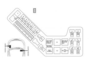
Engine fuse box of Quadrajet
 TATA Indigo Manzda – fuse box – engine compartment (Quadrajet)
| Fuse |
Ampere rating [A] |
Function |
| 1 |
30 |
Fan 1 |
| 2 |
30 |
Fan 2 |
| 3 |
15 |
HI low beam |
| 4 |
15 |
HI high beam |
| 5 |
30 |
Contact main relay |
| 6 |
15 |
Coil main relay |
| 7 |
20 |
ECU & sensor W/H |
| 8 |
10 |
Fuel filter & ECU |
| 9 |
10 |
Glow plug timer |
| 10 |
15 |
Fuel pump relay |
| 11 |
10 |
ECU |
| 12 |
25 |
ABS |
| Fuse |
Ampere rating [A] |
Function |
| 1 |
60 |
Fan 1 |
| 2 |
BLANK |
BLANK |
| 3 |
60 |
Fan 1 & fan 2 |
| 4 |
60 |
Alternator, GPT |
| 5 |
60 |
Ignition |
| 6 |
60 |
ACC |
| 7 |
BLANK |
BLANK |
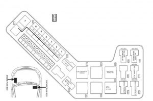
Engine fuse box of Safire
 TATA Indigo Manzda – fuse box – engine compartment (Safire)
| Fuse |
Ampere rating [A] |
Function |
| 1 |
BLANK |
BLANK |
| 2 |
30 |
Series fan relay |
| 3 |
15 |
HI low beam |
| 4 |
15 |
HI high beam |
| 5 |
30 |
Main relay |
| 6 |
15 |
Main relay coil |
| 7 |
BLANK |
BLANK |
| 8 |
10 |
ECU |
| 9 |
10 |
ECU (TBA) |
| 10 |
20 |
Series relay/fuel pump |
| 11 |
10 |
ECU |
| 12 |
25 |
ABS |
| Fuse |
Ampere rating [A] |
Function |
| 1 |
60 |
Fan 1 |
| 2 |
40 |
ECU |
| 3 |
60 |
Series fan relay |
| 4 |
60 |
Main RLY/ECU |
| 5 |
60 |
Ignition |
| 6 |
60 |
HEAD LAMP/BLOWER |
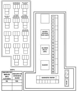
Fuse box
 TATA Indigo Manzda – fuse box
| Fuse |
Function |
Ampere rating [A] |
| 1 |
HORN |
15 |
| 2 |
ROOF, ENGINE & LOAD AREA LAMP |
5 |
| 3 |
MUSIC SYSTEM ,CLOCK & INSTRUMENT CLUSTER |
15 |
| 4 |
STOP LAMP & HIGH MOUNTED STOP LAMP |
10 |
| 5 |
HEATED RR WINDOWS |
25 |
| 6 |
IMMOBILIZER & DIAGNOSTIC |
5 |
| 7 |
CDL |
10 |
| 8 |
COIL BLOWER RELAY |
5 |
| 9 |
MOBILE CHARGER & REVERSE LAMP (SENSER W/H) |
15 |
| 10 |
CASSETTE PLAYER & RADIO |
10 |
| 11 |
POSITION LAMP LH |
5 |
| 12 |
POSITION LAMP RH |
5 |
| 13 |
FOG LAMP |
15 |
| 14 |
BCM |
20 |
| 15 |
H/L RLY COIL |
10 |
| 16 |
AC CONTROLS |
10 |
| 17 |
VENTILATION MOTOR, HVAC |
30 |
| 18 |
WASH & WIPERS |
20 |
| 19 |
INST. CLUSTER, FUEL CUT OFF |
10 |
| 20 |
ABS |
10 |
WARNING: Terminal and harness assignments for individual connectors will vary depending on vehicle equipment level, model, and market.


