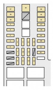
| Fuse |
Ampere rating [A] |
Circuit |
| 1 |
MIR HTR |
15 |
Outside rear view mirror heaters |
| 2 |
FOG |
15 |
Front fog lights |
| 3 |
TOW BRK |
30 |
Trailer brake controller |
| 4 |
SUB BATT |
30 |
Trailer sub battery |
| 5 |
TOW TAIL |
30 |
Trailer lights (tail lights) |
| 6 |
PWR OUTLET 1 |
15 |
Power outlet |
| 7 |
ECU–B |
5 |
Anti–lock brake system |
| 8 |
H–LP RH |
10 |
Right–hand headlight (high beam) |
| 9 |
PWR OUTLET 2 |
15 |
Power outlet |
| 10 |
DOME |
10 |
Interior light, personal lights, vanity light, ignition switch light, step light, door courtesy lights, open door warning light |
| 11 |
H–LP LH |
10 |
Left–hand headlight (high beam) |
| 12 |
EFI NO.2 |
10 |
Multiport fuel injection system/sequential multiport fuel injection system, emission control system |
| 13 |
RADIO |
20 |
Audio system |
| 14 |
HEAD RL |
10 (with daytime running light system) |
Right–hand headlight (low beam) |
| 15 |
A/C |
10 |
Air conditioning system |
| 16 |
HEAD LL |
10 (with daytime running light system) |
Left–hand headlight (low beam) |
| 17 |
ALT–S |
7,5 |
Charging system |
| 18 |
ETCS |
10 (2UZ–FE engine) |
Multiport fuel injection system/sequential multiport fuel injection system, electronic throttle control system |
| 19 |
HAZ |
15 |
Emergency flashers |
| 20 |
EFI NO. 1 |
20 |
Multiport fuel injection system/sequential multiport fuel injection system, fuel pump, “EFI NO.2” fuse |
| 21 |
AM2 |
30 |
Ignition system, starting system, “IGN” and “STA” fuses |
| 22 |
TOWING |
30 |
Towing converter |
| 23 |
ETCS |
15 (5VZ–FE engine) |
Multiport fuel injection system/sequential multiport fuel injection system, electronic throttle control system |
| 24 |
WIP |
20 |
Windshield wipers and washer |
| 25 |
TURN |
5 |
Turn signal lights |
| 26 |
ECU IG |
5 |
Anti–lock brake system, cruise control system |
| 27 |
4WD |
20 |
Four–wheel drive control system, A.D.D. control system |
| 28 |
ACC |
15 |
Cigarette lighter, audio system, SRS airbag system, power rear view mirrors, “PWR OUTLET 1” and “PWR OUTLET 2” fuses |
| 29 |
GAUGE |
10 |
Gauges and meters, back–up lights, starting system, air conditioning system |
| 30 |
IGN |
5 |
SRS airbag system, multiport fuel injection system/sequential multiport fuel injection system, discharge warning light, ignition system |
| 31 |
CARGO LP |
5 |
Cargo lamp |
| 32 |
TAIL |
15 |
Tail lights, license plate lights, instrument panel lights, parking lights, glove box light |
| 33 |
OBD |
7,5 |
On–board diagnosis system |
| 34 |
HORN |
10 |
Horns |
| 35 |
STA |
5 |
Multiport fuel injection system/sequential multiport fuel injection system, gauges and meters |
| 36 |
STOP |
15 |
Stoplights, high mounted stoplight |
