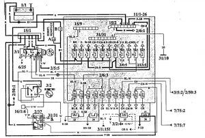
Volvo 740 (1992) – fuse box diagram
Year of production: 1992
Fuse box diagram

| Number | Description |
| 1/1 | Battery |
| 2/5 | Relay, seat belt reminder |
| 2/6 | Bypass relay 151 |
| 2/13 | Relay, fuel injection |
| 2/37 | Headlight relay |
| 2/50 | Bypass relay, high beam |
| 3/1 | Ignition lock |
| 3/2 | Light switch |
| 3/5 | Switch, turn signal/high – low beam |
| 3/7 | Fog light switch |
| 6/25 | Starter motor |
| 7/75 | Bulb failure sensor |
| 11/1-26 | Fuses |
| 15/1 | Positive terminal |
| 15/2 | 30-traial in central electrical unit |
| 15/9 | Fused 15-traial in central electrical unit |
| 16/1 | Radio |
| 31/10 | Ground connection, right A-post |
| 31/31 | Ground connection rail in central electrical unit |
| A | Connector, left A-post |
| B | Connector, right A-post |
| Position | Function | Ampere rating [A] |
| 1 | Fuel pump (LH-2.4), Fuel system, Ignition system, Lambda sonda pre-heating (B200/230FT) | 25 |
| 2 | Central locking, Hazard warning flashers, Headlight flashers (via fuses 17 and 18) | 25 |
| 3 | Power seats | — |
| 4 | Brake lights, solenoid shift-lock | 15 |
| 5 | Clock, Vanity mirror lighing, Glove compartment lighting, truck light, Interior light, Radio, Power antenna, door-open warning lights | 15 |
| 6 | Electronic climate unit ECC, Compartment fan, electronic climate unit ECC | 30 |
| 7 | Front fog lights, Rear fog lights (not 740 USA, Canada) | 30 |
| 8 | Power windows | 30 |
| 9 | Turn signal, control lamps for seat belts, seat belt reminder, key warning, bypass relay 151 (powetr windows/seat heater), relay P-shift lock | 15 |
| 10 | Heated rear window Power-operated sunroof, Heated door mirrors | 30 |
| 11 | Fuel primer pump in rank (LH-2.4), fuel pump in tank (Regina), Lambda-sond pre-heating | 15 |
| 12 | Back-up lights, overdrive relay, bulb failure sensor with brake circuit sensor, Exhaust temperature sensor (Japan), Cruise control | 15 |
| 13 | Fuel valve, diesel, pre-heating system, diesle, Charge pressure limiter, turbodiesel, EGR diesel | 15 |
| 14 | Power door mirrors, Cigar lighter, Radio, Tailgate wash, Tailgate wiper | 15 |
| 15 | Relays, power seats, Horn, Windshield washer, Headlight washer | 25 |
| 16 | Component fan, standard heater, Component fan, manual climate unit MCC, Electronic climate unit ECC | 30 |
| 17 | Left high beam, Control lamp, high beam | 15 |
| 18 | Right high beam, Relay front fog light | 15 |
| 19 | Left low beam, Beam length control, Relay, front fog light | 15 |
| 20 | Right low beam, Beam length control | 15 |
| 21 | Left parking lights, front and rear; Number late lighting, Instrument and control illumination | 15 |
| 22 | Relay, front fog light, Right parking light, front and rear, Ashtray lighting, rear, Gear selector lighting, automatic gearbox, Lighting, switches and storage compartment, tunnel console | 15 |
| 23 | Heated front seats | 25 |
| 24 | Spare (SRS test socket) | — |
| 25 | Rear fog lights (740 USA, Canada), Cutout for low beam (Sweden, Norway, Denmark) | 15 |
| 26 | Amplifier, Radio | 15 |
| A | Connector, left A-post | |
| B | Connector, right A-post |
WARNING: Terminal and harness assignments for individual connectors will vary depending on vehicle equipment level, model, and market.
