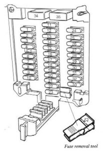
Volvo 960 (1992) – fuse box diagram
Year of production: 1992
Fuse box

| Number | Description |
| 1/1 | Battery |
| 2/1 | Headlight relay |
| 2/11 | Electric fan |
| 2/13 | Relay Motronic, I.II-jetronic |
| 3/1 | Ignition switch |
| 3/2 | Headlight switch |
| 3/3 | Dipped/main beam switch |
| 4/9 | Crash sensor SRS |
| 5/3 | 3-pole connector for combined instrument panel |
| 5/12 | 12-pole connector for combined instrument panel |
| 6/31 | Fuel pump |
| 7/1 | Bulb failure warning sensor rear |
| 11/1-35 | Fuses |
| 15/1 | Positive terminal |
| 15/3 | 30 strip in fusebox |
| 15/7 | Ground contact strip via door switch |
| 19/4 | Clock |
| A | Connector, left A-post (Connector, right A-post, B280F/F) |
| Position | Function | Ampere rating [A] |
| 1 | Left parking lights, license plate light, rear parking lights | 10 |
| 2 | Right parking lights | 10 |
| 3 | Left high beam | 15 |
| 4 | Right high beam | 15 |
| 5 | SRS test | — |
| 6 | Left low beam | 15 |
| 7 | Right low beam | 10 |
| 8 | Front fog lights | 15 |
| 9 | Rear fog lights | 10 |
| 10 | Instrument/panel lighting | 5 |
| 11 | Back-up lights, turn signals, cruise control | 15 |
| 12 | Shift lock | 15 |
| 13 | Heated rear window, heated door mirrors | 25 |
| 14 | Overdrive, relays for power windows/sunroof/heated seats/seat belt reminder | 10 |
| 15 | Spare | — |
| 16 | Heated seats | 30 |
| 17 | Spare | — |
| 18 | Radio/cassette tape player | 5 |
| 19 | ECC, power windows, rear wiper/washer (wagons), cigarette lighter, power seats | 15 |
| 20 | Windshield wipers/washers, horn | 25 |
| 21 | Transmission mode selectors, diagnostic socket, cooling fan, EGR valve | 5 |
| 22 | ABS | 5 |
| 23 | Transmission control | 10 |
| 24 | Transmission/engine controls | 10 |
| 25 | Hazard warning flashers, central locking system | 25 |
| 26 | Clock, interior lighting, door open warning lights, cargo space and vanity mirrors | 10 |
| 27 | Brake lights, shiftlock release | 15 |
| 28 | ECC, air conditioning | 30 |
| 29 | Power antenna, electrical connector for trailer | 30 |
| 30 | Fuel pump (tank), electrically heated Lambda sond | 10 |
| 31 | Fuel injection, fuel pump (main), ignition | 25 |
| 32 | Radio/amplifier, optional equipment | 10 |
| 33 | Radio/cassette tape player | 10 |
| 34 | Power windows, power sun roof | 30 |
| 35 | Power seats | 30 |
| he ABS system is protected by an additional fuse which is located under the instrument panel to the left of the steering wheel. | 10 | |
WARNING: Terminal and harness assignments for individual connectors will vary depending on vehicle equipment level, model, and market.