Volvo S60 mk1 (First Generation; 2004) – fuse box diagram
Year of production: 2004
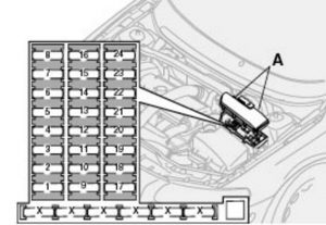
Fuse box in the engine compartment

engine compartment
| Position | Function | Ampere rating [A] |
| 1 | Accessories | 25 |
| 2 | Auxiliary lights (option) | 20 |
| 3 | — | — |
| 4 | Oxygen sensor | 20 |
| 5 | Crankcase ventilation heater, solenoid valves | 10 |
| 6 | Mass air flow sensor, engine control module, injectors | 15 |
| 7 | Throttle module | 10 |
| 8 | A/C compressor, accelerator pedal position sensor, E-box fan | 10 |
| 9 | Horn | 15 |
| 10 | — | — |
| 11 | A/C compressor, ignition coils | 20 |
| 12 | Brake light switch | 5 |
| 13 | Windshield wipers | 25 |
| 14 | ABS/STC/DSTC | 30 |
| 15 | — | — |
| 16 | Windshield washers, headlight wipers/washers (certain models) | 15 |
| 17 | Low beam, right | 10 |
| 18 | Low beam, left | 10 |
| 19 | ABS/STC/DSTC | 30 |
| 20 | High beam, left | 15 |
| 21 | High beam, right | 15 |
| 22 | Starter motor | 35 |
| 23 | Engine control module | 10 |
| 24 | — | 5 |
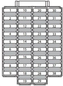
Fuse box on the edge of the dashboard

| Position | Function | Ampere rating [A] |
| 1 | Low beam headlights | 15 |
| 2 | High beam headlights | 20 |
| 3 | Power driver’s seat | 30 |
| 4 | Power passenger’s seat | 30 |
| 5 | Speed-dependent power steering, vacuum pump | 15 |
| 6 | — | — |
| 7 | Heated seat, front left (option) | 15 |
| 8 | Heated seat, front right (option) | 15 |
| 9 | ABS/STC/DSTC | 5 |
| 10 | Daytime running lights | 10 |
| 11 | Daytime running lights | 10 |
| 12 | Headlight wipers (certain models) | 15 |
| 13 | Electric socket 12V | 15 |
| 14 | Power passenger’s seat | 5 |
| 15 | Audio system, VNS | 5 |
| 16 | Audio system | 20 |
| 17 | Audio amplifier | 30 |
| 18 | Front fog lights | 15 |
| 19 | VNS display | 10 |
| 20 | — | — |
| 21 | Automatic transmission, shiftlock, extended D2 feed | 10 |
| 22 | Direction indicators | 20 |
| 23 | Headlight switch module, climate control system, onboard diagnostic connector, steering wheel lever modules | 5 |
| 24 | Relay extended D1 feed: climate control system, power driver’s seat, driver’s info | 10 |
| 25 | Ignition switch, relay starter motor, SRS, engine control module | 10 |
| 26 | Climate control system blower | 30 |
| 27 | Active chassis FOUR-C | 15 |
| 28 | Electronic module – courtesy lighting | 10 |
| 29 | — | — |
| 30 | Left front/rear parking lights | 7,5 |
| 31 | Right front/rear parking lights, license plate lights | 7,5 |
| 32 | Central electrical module, vanity mirror lighting, glove compartment light, interior courtesy lighting | 10 |
| 33 | Fuel pump | 15 |
| 34 | Power moonroof | 15 |
| 35 | Central locking system, power windows, left door mirror | 25 |
| 36 | Central locking system, power windows, right door mirror | 25 |
| 37 | Rear power windows | 30 |
| 38 | Alarm siren* | 5 |
| * Please be aware that if this fuse is not intact, or if it is removed, the alarm will sound. | ||
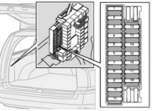
Fuses in the trunk

trunk
| Position | Function | Ampere rating [A] |
| 1 | Rear electrical module, trunk lighting | 10 |
| 2 | Rear fog light | 10 |
| 3 | Brake light | 15 |
| 4 | Backup lights | 10 |
| 5 | Rear window defroster, Relay 15I – accessories | 5 |
| 6 | Trunk release | 10 |
| 7 | Folding rear head restraints | 10 |
| 8 | Central locking rear doors, fuel filler door | 15 |
| 9 | Trailer hitch (30 feed) | 15 |
| 10 | CD changer, VNS | 10 |
| 11 | Accessory control module (AEM) | 15 |
| 12 | — | — |
| 13 | — | — |
| 14 | Brake lights | 7,5 |
| 15 | Trailer hitch (15I feed) | 20 |
| 16 | Electric socket in trunk – accessories | 15 |
| 17 | All Wheel Drive control module | 7,5 |
| 18 | — | — |
WARNING: Terminal and harness assignments for individual connectors will vary depending on vehicle equipment level, model, and market.
