Volvo S80 mk2 (Second Generation; 2016) – fuse box diagram
Year of production: 2016
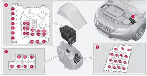
Fuses – engine compartment
A – Engine compartment, upper
B – Engine compartment, front
C – Engine compartment, lower

| Position | Function | Ampere rating [A] |
| 1 | Circuit breaker: central electrical module under the glove compartment A | 50 |
| 2 | Circuit breaker: central electrical module under the glove compartment | 50 |
| 3 | Circuit breaker: central electrical module in the trunk A | 60 |
| 4 | Circuit breaker: central electrical module under the glove compartment A | 60 |
| 5 | Circuit breaker: central electrical module under the glove compartment A | 60 |
| 6 | — | — |
| 7 | — | — |
| 8 | Headed windshield*, driver’s side | 40 |
| 9 | Windshield wipers | 30 |
| 10 | — | — |
| 11 | Climate system blower A | 40 |
| 12 | Headed windshield*, passenger’s side | 40 |
| 13 | ABS pump | 40 |
| 14 | ABS valves | 20 |
| 15 | Headlight washers | 20 |
| 16 | Active Bending Lightsheadlight leveling* | 10 |
| 17 | Central electrical module (under the glove compartment) | 20 |
| 18 | ABS | 5 |
| 19 | Adjustable steering force* | 5 |
| 20 | Engine Control Module (ECM), transmission, SRS | 10 |
| 21 | Heated washer nozzles* | 10 |
| 22 | — | — |
| 23 | Lighting panel | 5 |
| 24 | — | — |
| 25 | — | — |
| 26 | — | — |
| 27 | Relay coils | 5 |
| 28 | Auxiliary lights* | 20 |
| 29 | Horn | 15 |
| 30 | Relay coils, Engine Control Module (ECM) | 10 |
| 31 | Control module – automatic transmission | 15 |
| 32 | A/C compressor (not 4- cyl. engines) | 15 |
| 33 | Relay-coils A/C, relay coils in engine compartment cold zone for Start/Stop | 5 |
| 34 | Starter motor relay A | 30 |
| 35 | Engine control module (4- cyl. engines), Ignition coils (5 cyl. engines) | 20 |
| 36 | Engine Control Module (4- cyl. engines) | 20 |
| Engine Control Module (5- cyl. engines) | 10 | |
| 37 | 4-cyl. engines: mass air meter, thermostat, EVAP valve | 10 |
| 5-cyl. engines: Injection system, engine control module | 15 | |
| 38 | A/C compressor (5-/6- cyl. engines), engine valves, engine control module (6-cyl. engines), solenoids (6- cyl. non-turbo only), mass air meter (6-cyl. only), oil level sensor (5-cyl. only) | 10 |
| Engine valves/oil pump/ center heated oxygen sensor (4-cyl. engines) | 15 | |
| 39 | Front/rear heated oxygen sensors (4-cyl. engines), EVAP valve (5-/6-cyl. engines), heated oxygen sensors (5-/6-cyl. engines) | 15 |
| 40 | Oil pump/crankcase ventilation heater/coolant pump (5-cyl. engines) | 10 |
| Ignition coils (4-cyl. engines) | 15 | |
| 41 | Fuel leakage detection (5-/6-cyl. engines), control module for radiator shutter (5-cyl. engines) | 5 |
| Fuel leakage detection, A/C solenoid (4-cyl. engines) | 7,5 | |
| 42 | Coolant pump (4-cyl. engines) | 50 |
| 43 | Cooling fan | 60 or 80 (4-cyl. engines) |
| 60 (5-cyl. engines) | ||
| 44 | Power steering | 100 |
| * – Option/accessory, for more information, see Introduction | ||
| A – This position is not used on vehicles with the optional Start/ Stop function | ||
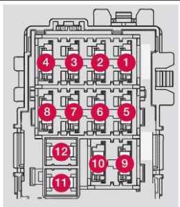
Fuses – glove compartment

Fusebox A: General fuses
Fusebox B: Control module fuses
Positions: fusebox A
| Position | Function | Ampere ratting [A] |
| 1 | Circuit breaker for the infotainment system and for fuses 16-20 | 40 |
| 2 | — | — |
| 3 | — | — |
| 4 | Heated steering wheel* | 10 |
| 5 | Analog clock (Executive) | 5 |
| 6 | — | — |
| 7 | 12-volt socket (trunk), refrigerator (S80 Executive only) | 15 |
| 8 | Controls in driver’s door | 20 |
| 9 | Controls in front passenger’s door | 20 |
| 10 | Controls in right rear passenger’s door | 20 |
| 11 | Controls in left rear passenger’s door | 20 |
| 12 | Keyless drive* | 20 |
| 13 | Power driver’s seat* | 20 |
| 14 | Power front passenger’s seat* | 20 |
| 15 | — | — |
| 16 | Infotainment system display | 5 |
| 17 | Infotainment system: amplifier, SiriusXM™ satellite radio* | 10 |
| 18 | Sensus control module | 15 |
| 19 | Bluetooth hands-free system | 5 |
| 20 | — | — |
| 21 | Power moonroof* Courtesy lighting, climate system sensor | 5 |
| 22 | 12-volt sockets in tunnel console | 15 |
| 23 | Heated rear seat* (passenger’s side) | 15 |
| 24 | Heated rear seat* (driver’s side) | 15 |
| 25 | — | — |
| 26 | Heated front passenger’s seat* | 15 |
| 27 | Heated driver’s seat* | 15 |
| 28 | Park assist* | 5 |
| 29 | All Wheel Drive* control module | 15 |
| 30 | Active chassis system* | 10 |
Positions: fusebox B
| Position | Function | Ampere ratting [A] |
| 1 | — | — |
| 2 | — | — |
| 3 | Front courtesy lighting, driver’s door power window controls, power seat(s)* | 7,5 |
| 4 | Instrument panel | 5 |
| 5 | Adaptive cruise control/collision warning* | 10 |
| 6 | Courtesy lighting, rain sensor*, HomeLInk® Wireless Control System* | 7,5 |
| 7 | Steering wheel module | 7,5 |
| 8 | Cental locking: fuel filler door | 10 |
| 9 | — | — |
| 10 | Windshield washers | 15 |
| 11 | Trunk open | 10 |
| 12 | Electrical folding rear seat outboard head restraints* | 10 |
| 13 | Fuel pump | 20 |
| 14 | Climate system control panel | 5 |
| 15 | — | — |
| 16 | Alarm, On-board diagnostic system | 5 |
| 17 | Satellite radio *, audio system amplifier | 10 |
| 18 | Airbag system, occupant weight sensor | 10 |
| 19 | Collision warning system* | 5 |
| 20 | Accelerator pedal sensor, autodim mirror function, heated rear seats* | 7,5 |
| 21 | — | — |
| 22 | Brake lights | 5 |
| 23 | Power moonroof* | 20 |
| 24 | Immobilizer | 5 |
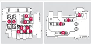
Fuses – cargo area/trunk

| Position | Function | Ampere rating [A] |
| 1 | Electric parking brake (left side) | 30 |
| 2 | Electric parking brake (right side) | 30 |
| 3 | Heated rear window | 30 |
| 4 | Trailer socket 2* | 15 |
| 5 | — | — |
| 6 | — | — |
| 7 | — | — |
| 8 | — | — |
| 9 | — | — |
| 10 | — | — |
| 11 | Trailer socket 1* | 40 |
| 12 | — | — |
Fuses – engine compartment cold zone (Start/Stop only)

| Position | Function | Ampere ratting [A] |
| A1 | Circuit breaker: central electrical module in the engine compartment | 175 |
| A2 | Circuit breaker: fuseboxes under the glove compartment, central electrical module in the trunk | 175 |
| 1 | — | — |
| 2 | Circuit breaker: fusebox B under the glove compartment | 50 |
| 3 | Circuit breaker: fusebox A under the glove compartment | 60 |
| 4 | Circuit breaker: fusebox A under the glove compartment | 60 |
| 5 | Circuit breaker: central electrical module in the trunk | 60 |
| 6 | Climate system blower | 40 |
| 7 | — | — |
| 8 | — | — |
| 9 | Starter motor relay | 30 |
| 10 | Internal diode | 50 |
| 11 | Auxiliary battery | 70 |
| 12 | Central electrical module: auxiliary battery reference voltage, auxiliary battery charging poin | 15 |
WARNING: Terminal and harness assignments for individual connectors will vary depending on vehicle equipment level, model, and market.
