Volvo V60 (2020) – fuse and relay box diagram
Year of production: 2020
The Volvo V60 (2020) is a premium midsize luxury wagon, combining Volvo’s renowned safety features with a blend of Scandinavian design, versatile practicality, and advanced technology. Continuing the success of the second-generation model launched in 2019, the 2020 V60 offers a range of powertrains, including fuel-efficient engines and a plug-in hybrid option, making it a sophisticated choice for those seeking both performance and eco-friendliness.
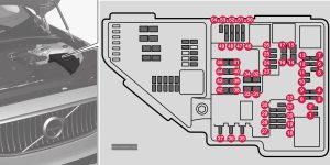
Engine compartment
Fuse box location and diagram

Assignment of fuses in the engine compartment (2020)
| № | Ampere | Function |
|---|---|---|
| 1 | – | – |
| 2 | – | – |
| 3 | – | – |
| 4 | 15 | Ignition coils (petrol); Spark plugs (petrol); Exhaust sensor; Diesel particle sensor |
| 5 | 15 | Solenoid for engine oil pump; Solenoid clutch A/C; Lambda probe, centre (petrol); Lambda probe, rear (diesel); Lambda probe, front (petrol/diesel) |
| 6 | 7,5 | Vacuum regulators; Valve; Valve for output pulse (diesel); Oil level/temperature sensor (diesel); Glow plugs (GCU) (diesel) |
| 7 | 20 | Engine control module; Actuator; Throttle unit; EGR valve (diesel); Position sensor for turbo (diesel); Valve for turbocharger (petrol) |
| 8 | 5 | Engine Control Module (ECM) |
| 9 | – | – |
| 10 | 10 | Solenoids (petrol); Valve; Thermostat for engine cooling system (petrol); Cooling pump for EGR (diesel); Glow control unit (diesel); Supercharger clutch (petrol); Crankshaft ventilation heater (diesel); Valve, gearbox oil cooler (diesel) |
| 11 | 5 | Control module for spoiler damper; Control module for radiator damper; Relay coils for output pulse (diesel) |
| 12 | 15 | Coolant pump |
| 13 | 20 | Engine Control Module (ECM) |
| 14 | 40 | Starter motor |
| 15 | Shunt | Starter motor |
| 16 | 30 | Fuel filter heater (diesel) |
| 17 | – | – |
| 18 | 5 | Calculation unit |
| 19 | – | – |
| 20 | – | – |
| 21 | – | – |
| 22 | – | – |
| 23 | – | – |
| 24 | 15 | 12 V socket in tunnel console, front |
| 25 | 15 | 12 V socket in tunnel console, by legroom for second seat row |
| 26 | 15 | 12 V socket in cargo area |
| 27 | – | – |
| 28 | 15 | Left-hand headlamp, LED |
| 29 | 15 | Right-hand headlamp, LED |
| 30 | – | – |
| 31 | Shunt | Heated windscreen, left-hand side |
| 32 | 40 | Heated windscreen, left-hand side |
| 33 | 25 | Headlamp washers |
| 34 | 25 | Washer fluid pump |
| 35 | 15 | Transmission control unit; Electric gear selector |
| 36 | 20 | Horn |
| 37 | 5 | Siren |
| 38 | 40 | Control module for brake system (valves, parking brake) |
| 38 | 30 | Brake control with 48V battery |
| 39 | 30 | Windscreen wipers |
| 40 | 25 | Rear window washer |
| 41 | 40 | Heated windscreen, right-hand side |
| 42 | 20 | Parking heater |
| 43 | – | – |
| 44 | – | – |
| 45 | Shunt | Heated windscreen, right-hand side |
| 46 | 5 | Supplied when the ignition is switched on: Engine control module; Transmission components; Electric steering servo; Central electronic module; Control module for brake system |
| 47 | – | – |
| 48 | 15 | Right-hand headlamp, LED |
| 49 | 5 | Alcohol lock |
| 50 | 10 | Transmission control module |
| 51 | 5 | Module for controlling battery engagement |
| 52 | 5 | Airbags; Passenger weight sensor |
| 53 | 15 | Left-hand headlamp, LED |
| 54 | 5 | Accelerator pedal sensor |
| 54 | 5 | Accelerator pedal sensor |
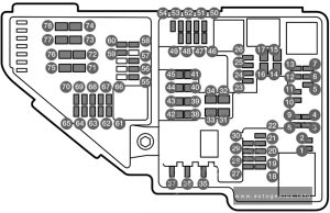
Engine compartment (Twin Engine) – fuse box diagram

Assignment of fuses in the engine compartment (2020, Twin Engine)
| № | Ampere | Function |
|---|---|---|
| 1 | – | – |
| 2 | – | – |
| 3 | – | – |
| 4 | 5 | Control module for actuator for engagement/change of automatic gearbox gear positions |
| 5 | 5 | Control module for the high-voltage heater of the internal combustion engine’s coolant |
| 6 | 5 | Control module for air conditioning; Shut-off valve for heat exchanger; Shut-off valve for coolant that passes through the climate control system |
| 7 | 5 | Control module for hybrid battery; High voltage converter for combined high-voltage generator/starter motor with voltage converter 500V-12V |
| 8 | – | – |
| 9 | 10 | Converter for control of the supply to the rear axle’s electric motor |
| 10 | 10 | Control module for hybrid battery; High voltage converter for combined high-voltage generator/starter motor with voltage converter 500V-12V |
| 11 | 5 | Charging unit |
| 12 | 15 | Shut-off valve for the hybrid battery’s coolant; Coolant pump 1 for hybrid battery |
| 13 | 15 | Coolant pump for electric drive system |
| 14 | 25 | Cooling fan for hybrid components |
| 15 | – | – |
| 16 | – | – |
| 17 | – | – |
| 18 | 5 | Calculation unit |
| 19 | – | – |
| 20 | – | – |
| 21 | – | – |
| 22 | – | – |
| 23 | – | – |
| 24 | 15 | 12 V socket in tunnel console, front |
| 25 | 15 | 12 V socket in tunnel console, by legroom for second seat row |
| 26 | 15 | 12 V socket in cargo area, USB ports in head restraints right/left |
| 27 | – | – |
| 28 | 15 | Left-hand headlamp, LED |
| 29 | 15 | Right-hand headlamp, LED |
| 30 | – | – |
| 31 | Shunt | Heated windscreen, left-hand side |
| 32 | 40 | Heated windscreen, left-hand side |
| 33 | 25 | Headlamp washers |
| 34 | 25 | Windscreen washers |
| 35 | – | – |
| 36 | 20 | Horn |
| 37 | 5 | Siren |
| 38 | 40 | Control module for brake system (valves, parking brake) |
| 39 | 30 | Windscreen wipers |
| 40 | 25 | Rear window washer |
| 41 | 40 | Heated windscreen, right-hand side |
| 42 | 20 | Parking heater |
| 43 | 40 | Control unit for brake system (ABS pump) |
| 44 | – | – |
| 45 | Shunt | Heated windscreen, right-hand side |
| 46 | 5 | Supplied when the ignition is switched on: Engine control module; Transmission components; Electric steering servo; Central electronic module |
| 47 | 5 | Exterior car noise (certain markets) |
| 48 | 15 | Right-hand headlamp, LED |
| 49 | 5 | Alcohol lock |
| 50 | – | – |
| 51 | – | – |
| 52 | 5 | Airbags; Passenger weight sensor |
| 53 | 15 | Left-hand headlamp, LED |
| 54 | 5 | Accelerator pedal sensor |
| 55 | 15 | Transmission control module; Control module for gear selector |
| 56 | 5 | Engine Control Module (ECM) |
| 57 | – | – |
| 58 | – | – |
| 59 | – | – |
| 60 | – | – |
| 61 | 20 | Engine control module; Actuator; Throttle unit; Valve for turbocharger |
| 62 | 10 | Solenoids; Valves; Overpressure connection |
| 63 | 7,5 | Vacuum regulators; Valve for electric bypass: Valve for ventilation |
| 64 | 5 | Control unit, spoiler damper; Control unit, radiator damper |
| 65 | – | – |
| 66 | 15 | Lambda probe, front and rear |
| 67 | 15 | Solenoid for engine oil pump; Solenoid clutch A/C; Lambda probe, front, centre and rear |
| 68 | – | – |
| 69 | 20 | Engine Control Module (ECM) |
| 70 | 15 | Ignition coils; Spark plugs |
| 71 | – | – |
| 72 | – | – |
| 73 | 30 | Control module for transmission fluid pump |
| 74 | – | – |
| 75 | 25 | Actuator for transmission |
| 76 | – | – |
| 77 | – | – |
| 78 | – | – |
| 77 | – | Not Used |
| 78 | – | Not Used |
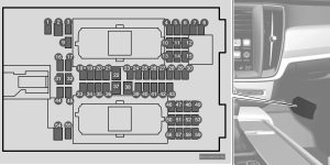
Passenger compartment
Fuse box location and diagram

Assignment of fuses under the glove compartment (2020)
| № | Ampere | Function |
|---|---|---|
| 1 | 10 | Intermediate voltage module |
| 2 | 30 | Electrical socket in tunnel console, by legroom for rear seat |
| 3 | – | – |
| 4 | 5 | Movement detector |
| 5 | 5 | Media player |
| 6 | 5 | Driver display |
| 7 | 5 | Keypad in centre console |
| 8 | 5 | Sun sensor |
| 9 | – | – |
| 10 | – | – |
| 11 | 5 | Steering wheel module |
| 12 | 5 | Module for start knob and for parking brake control |
| 13 | 15 | Steering wheel module for heated steering wheel |
| 14 | – | – |
| 15 | – | – |
| 16 | – | – |
| 17 | – | – |
| 18 | 10 | Control module for climate control system |
| 19 | 7,5 | Steering lock |
| 20 | 10 | Diagnostic socket OBDII |
| 21 | 5 | Centre display |
| 22 | 40 | Fan module for climate control system, front |
| 23 | 5 | USB HUB |
| 24 | 7,5 | Controls lighting; Interior lighting; Dimming of interior rearview mirror; Rain and light sensor; Keypad in tunnel console, by legroom for rear seat; Power front seats; Control panels in rear doors; Fan module for climate control left/right |
| 25 | 5 | Control module for driver support functions |
| 26 | 20 | Panorama roof with sun blind |
| 27 | 5 | Head-up display |
| 28 | 5 | Passenger compartment lighting |
| 29 | – | – |
| 30 | 5 | Display in roof console (Seatbelt reminder/lndicator for airbag on the front passenger seat) |
| 31 | – | – |
| 32 | – | – |
| 33 | 20 | Door module in right-hand rear door |
| 34 | 10 | Fuses in cargo area |
| 35 | 5 | Control module for online car; Control module for Volvo On Call |
| 36 | Door module in left-hand rear door | |
| 37 | 40 | Audio control device (amplifier) |
| 38 | – | – |
| 39 | 5 | Module for multi-band antenna |
| 40 | 5 | Modules for seat comfort (massage) front |
| 41 | 5 | Alcohol lock |
| 42 | 15 | Rear window wiper |
| 43 | 15 | Control module for fuel pump |
| 44 | 5 | Twit Engine: Relay coils in fuse box in engine compartment; Relay coil for transmission oil pump; Medium voltage converter; Integrated dynamo |
| 45 | 5 | Opening the boot lid/tailgate with foot motion |
| 46 | 15 | Seat heating, driver’s side front |
| 47 | 15 | Seat heating, passenger side front |
| 48 | 7,5 | Coolant pump |
| 49 | – | – |
| 50 | 20 | Door module in left-hand front door Twin Engine: Power driver’s seat |
| 51 | 20 | Control module for suspension (active chassis) |
| 52 | – | – |
| 53 | 10 | Sensus control module |
| 54 | – | – |
| 55 | – | – |
| 56 | 20 | Door module in right-hand front door Twin Engine: Electrically operated front passenger seat |
| 57 | – | – |
| 58 | 5 | TV (certain markets) |
| 59 | 15 | Primary fuse for fuses 52, 53, 57 and 58 |
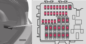
Cargo compartment
Fuse box location and diagram

Assignment of fuses in the trunk (2020)
| № | Ampere | Function |
|---|---|---|
| 1 | 30 | Rear window defroster |
| 2 | 40 | Twin Engine: Central electronic module |
| 3 | 40 | Compressor for air suspension |
| 4 | 15 | Lock motor for backrest on rear right-hand side |
| 5 | – | – |
| 6 | 15 | Lock motor for backrest on rear left-hand side |
| 7 | 20 | Electrically operated front passenger seat Door module right-hand side rear |
| 8 | 30 | Control module for reduction of nitrous oxides (diesel) |
| 9 | 25 | Power operated tailgate |
| 10 | 20 | Electrically operated front passenger seat Door module right-hand side front |
| 11 | 40 | Towbar control module |
| 12 | 40 | Seatbelt pretensioner module, right-hand side |
| 13 | 5 | Internal relay coils |
| 14 | 15 | Control module for reduction of nitrous oxides (diesel) |
| 15 | 20 | Door module left-hand side rear |
| 16 | 5 | Alcohol lock, USB hub/accessory port |
| 17 | 5 | Enhanced accessory module |
| 18 | 25 | Towbar control module |
| 18 | 40 | Accessory module |
| 19 | 20 | Power driver seat Door module left-hand side front |
| 20 | 40 | Seatbelt pretensioner module, left-hand side |
| 21 | 5 | Parking camera |
| 22 | – | – |
| 23 | – | – |
| 24 | – | – |
| 25 | 10 | Twin Engine: Supply when the ignition is switched on |
| 26 | – | – |
| 27 | – | – |
| 28 | 15 | Seat heating left-hand side rear |
| 29 | – | – |
| 30 | 5 | Blind Spot Information (BLIS) Control module, exterior reversing sound |
| 31 | – | – |
| 32 | 5 | Seatbelt pretensioner modules |
| 33 | 5 | Actuator for exhaust gases (petrol, certain engine variants) |
| 34 | – | – |
| 35 | 15 | All Wheel Drive (AWD) control module |
| 36 | 15 | Seat heating right-hand side rear |
| 37 | – | – |
WARNING: Terminal and harness assignments for individual connectors will vary depending on vehicle equipment level, model, and market.
