Volvo V60 (2021) – fuse and relay box diagram
Year of production: 2021
The Volvo V60 (2021) is a luxury midsize wagon that blends Scandinavian design, cutting-edge technology, and exceptional safety features. Known for its versatility and elegant style, the 2021 V60 offers a refined driving experience, practical cargo space, and a range of efficient powertrains, including plug-in hybrid options. As part of Volvo’s continued commitment to sustainability, the V60 is an eco-conscious choice that doesn’t sacrifice performance or luxury.
Engine compartment
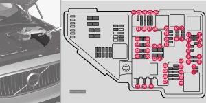
Fuse box location and diagram

Assignment of fuses in the engine compartment (2021)
| № | Ampere | Function |
|---|---|---|
| 1 | – | – |
| 2 | – | – |
| 3 | 15 | Lambda sensors; Electric charge pressure module |
| 4 | 15 | Ignition coils (gasoline); spark plugs (gasoline) Exhaust sensor; Diesel particulate sensor |
| 5 | 15 | Oil pump solenoid; A/C magnetic coupling; heated oxygen sensor, center (gasoline); heated oxygen sensor, rear (diesel); heated oxygen sensor, front (gasoline/diesel) |
| 6 | 7.5 | Vacuum regulator; Valve; Output pulse valve (diesel); Oil level/temperature sensor (gasoline/diesel); Glow plug (GCU) (diesel) |
| 7 | 20 | Engine control module; actuator; throttle unit; EGR valve (diesel); turbo position sensor (diesel); turbocharger valve (gasoline) |
| 8 | 5 | Engine control module |
| 9 | – | – |
| 10 | 10 | Solenoids (gasoline); Fuel leakage control valve; Engine cooling system thermostat (gasoline); EGR vacuum valve (diesel); Glow control module (diesel); Supercharger clutch (gasoline); Crankshaft ventilation heater (diesel); Transmission oil cooler valve (diesel) |
| 11 | 5 | Spoiler damper control module; Cooler damper control module; Relay coils for output pulse (diesel); Coolant valve Fuel leakage detection (gasoline) |
| 12 | 15 | Coolant pump |
| 13 | 20 | Engine control module |
| 14 | 40 | Starter motor |
| 15 | Shunt | Starter motor |
| 16 | 30 | Fuel filter heater (diesel) |
| 17 | – | – |
| 18 | 5 | Calculation module |
| 19 | – | – |
| 20 | – | – |
| 21 | 15 | ECM camera |
| 22 | – | – |
| 23 | 7.5 | Front USB port in tunnel console, rear |
| 24 | 15 | 12 V outlet in tunnel console, front |
| 25 | – | – |
| 26 | 15 | 12 V outlet in trunk/cargo compartment |
| 27 | – | – |
| 28 | 15 | Driver-side headlight, LED |
| 29 | 15 | Passenger-side headlight, LED |
| 30 | – | – |
| 31 | – | – |
| 32 | – | – |
| 33 | 25 | Headlight washers |
| 34 | 25 | Washer fluid pump |
| 35 | 15 | Transmission control module; Electric gear selector |
| 36 | 20 | Horn |
| 37 | 5 | Alarm siren |
| 38 | 40 | Brake system control module (valves, parking brake) |
| 38 | 30 | Brake control with 48 V battery |
| 39 | 30 | Wipers |
| 40 | 25 | Rear window washer |
| 41 | – | – |
| 42 | 20 | Parking heater |
| 43 | – | – |
| 44 | – | – |
| 45 | – | – |
| 46 | 5 | Fed when ignition is on: engine control module, transmission components, electrical power steering, central electrical module, brake system control module |
| 47 | – | – |
| 48 | 15 | Passenger-side headlight, LED |
| 49 | – | – |
| 50 | 10 | Transmission control module |
| 51 | 5 | Battery connection control module |
| 52 | 5 | Airbags; Passenger weight sensor |
| 53 | 15 | Driver-side headlight, LED |
| 54 | 5 | Accelerator pedal sensor |
| 54 | 5 | Accelerator pedal sensor |
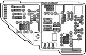
Engine compartment (Recharge PHEV) – fuse box diagram

Assignment of fuses in the engine compartment (2021, Recharge PHEV)
| № | Ampere | Function |
|---|---|---|
| 1 | – | – |
| 2 | – | – |
| 3 | – | – |
| 4 | 5 | Control module for actuator for engaging/changing gears, automatic transmission |
| 5 | 5 | High-voltage coolant heater control module |
| 6 | 5 | Control module for A/C; heat exchanger cut-off valve; cut-off valve for coolant through the climate system |
| 7 | 5 | Hybrid battery control module; high-voltage converter for combined high-voltage generator/starter motor with 500V-12V voltage converter |
| 8 | – | – |
| 9 | 10 | Converter for controlling feed to rear axle electric motor |
| 10 | 10 | Hybrid battery control module; high-voltage converter for combined high-voltage generator/starter motor with 500V-12V voltage converter |
| 11 | 5 | Charge module |
| 12 | 15 | Cut-off valve for hybrid battery coolant; coolant pump 1 for hybrid battery |
| 13 | 15 | Coolant pump for electric drive system |
| 14 | 25 | Hybrid component cooling fan |
| 15 | – | – |
| 16 | – | – |
| 17 | – | – |
| 18 | 5 | Calculation module |
| 19 | – | – |
| 20 | – | – |
| 21 | – | – |
| 22 | – | – |
| 23 | 7.5 | Front USB port in tunnel console, front |
| 24 | 15 | 12 V outlet in tunnel console, front |
| 25 | – | – |
| 26 | 15 | 12 V outlet in trunk/cargo compartment |
| 27 | – | – |
| 28 | 15 | Driver-side headlight, LED |
| 29 | 15 | Passenger-side headlight, LED |
| 30 | – | – |
| 31 | – | – |
| 32 | – | – |
| 33 | 25 | Headlight washers |
| 34 | 25 | Windshield washer |
| 35 | – | – |
| 36 | 20 | Horn |
| 37 | 5 | Alarm siren |
| 38 | 30 | Brake system control module (valves, parking brake) |
| 39 | 30 | Wipers |
| 40 | 25 | Rear window washer |
| 41 | – | – |
| 42 | 20 | Parking heater |
| 43 | – | – |
| 44 | – | – |
| 45 | – | – |
| 46 | 5 | Fed when ignition is on: Engine control module; transmission components, electrical power steering, central electrical module |
| 47 | 5 | Exterior vehicle sound (certain markets) |
| 48 | 15 | Passenger-side headlight, LED |
| 49 | – | – |
| 50 | – | – |
| 51 | – | – |
| 52 | 5 | Airbags; Passenger weight sensor |
| 53 | 15 | Driver-side headlight, LED |
| 54 | 5 | Accelerator pedal sensor |
| 55 | 15 | Transmission control module; gear selector control module |
| 56 | 5 | Engine control module |
| 57 | – | – |
| 58 | – | – |
| 59 | – | – |
| 60 | – | – |
| 61 | 20 | Engine control module; actuator; throttle unit; turbo-charger valve |
| 62 | 10 | Solenoids, Fuel leakage control valve; Overpressure coupling |
| 63 | 7.5 | Vacuum regulator; Electric bypass valve: Ventilation valve |
| 64 | 5 | Spoiler damper control module; Cooler damper control module Fuel leakage control pump |
| 65 | – | – |
| 66 | 15 | Heated oxygen sensor front and rear |
| 67 | 15 | Oil pump solenoid; A/C magnetic coupling; Heated oxygen sensor front, center and rear |
| 68 | – | – |
| 69 | 20 | Engine control module |
| 70 | 15 | Ignition coils; spark plugs |
| 71 | – | – |
| 72 | – | – |
| 73 | 30 | Transmission oil pump control module |
| 74 | – | – |
| 75 | – | – |
| 76 | – | – |
| 77 | – | – |
| 78 | – | – |
| 77 | – | Not Used |
| 78 | – | Not Used |
Passenger compartment
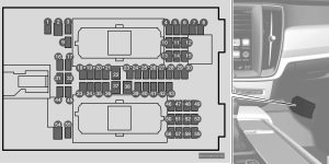
Fuse box location and diagram

Assignment of fuses under the glove compartment (2021)
| № | Ampere | Function |
|---|---|---|
| 1 | 10 | Medium voltage module (Vehicles with 48 V support battery only) |
| 2 | – | – |
| 3 | – | – |
| 4 | 5 | Movement sensor |
| 5 | – | – |
| 6 | 5 | Instrument panel |
| 7 | 5 | Center console buttons |
| 8 | 5 | Sun sensor |
| 9 | – | – |
| 10 | – | – |
| 11 | 5 | Steering wheel module |
| 12 | 5 | Module for start knob and parking brake controls |
| 13 | 15 | Heated steering wheel module |
| 14 | – | – |
| 15 | – | – |
| 16 | – | – |
| 17 | – | – |
| 18 | 10 | Climate system control module |
| 19 | – | – |
| 20 | 10 | Data link connector OBD-II |
| 21 | 5 | Center display |
| 22 | 40 | Climate system blower module (front) |
| 23 | 5 | USB HUB |
| 24 | 7.5 | Instrument lighting; Interior lighting; Rearview mirror auto-dim function; Rain and light sensors; Rear tunnel console keypad, rear seat; Power front seats; Rear door control panels; Climate system blower module left/right |
| 25 | 5 | Control module for driver support functions |
| 26 | 20 | Panoramic roof with sun curtain |
| 27 | 5 | Head-up display |
| 28 | 5 | Passenger compartment lighting |
| 29 | 5 | Wireless charging pad |
| 30 | 5 | Ceiling console display (seat belt reminder/front passenger side airbag indicator) |
| 31 | – | – |
| 32 | – | – |
| 33 | – | – |
| 34 | 10 | Fuses in the trunk/cargo compartment |
| 35 | 5 | Control module for Internet-connected vehicle; Control module for Volvo On Call |
| 36 | 20 | Door module in left-side rear door |
| 37 | 40 | Infotainment control module (amplifier) |
| 38 | – | – |
| 39 | 5 | Multi-band antenna module |
| 40 | 5 | Front seat massage function |
| 41 | – | – |
| 42 | 15 | Rear window wiper |
| 43 | 15 | Fuel pump control module |
| 44 | 5 | Relay coil for transmission oil pump Converter medium voltage; Integrated starter motor |
| 45 | 5 | Opening trunk/tailgate with foot movement |
| 46 | 15 | Driver’s seat heating |
| 47 | 15 | Front passenger’s seat heating |
| 48 | 7.5 | Coolant pump |
| 49 | – | – |
| 50 | 20 | Door module in left-side front door Recharge PHEV: Power driver’s seat |
| 51 | 20 | Active chassis control module |
| 52 | – | – |
| 53 | 10 | Sensus control module |
| 54 | – | – |
| 55 | – | – |
| 56 | 20 | Door module in right-side front door Recharge PHEV: Power front passenger seat |
| 57 | – | – |
| 58 | 5 | TV (certain markets only) |
| 59 | 15 | Primary fuse for fuses 52, 53, 57 and 58 |
Cargo compartment
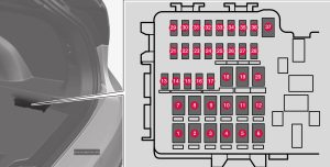
Fuse box location and diagram

Assignment of fuses in the trunk (2021)
| № | Ampere | Function |
|---|---|---|
| 1 | – | – |
| 2 | 40 | Recharge PHEV: Central electrical module |
| 3 | 40 | Pneumatic suspension compressor |
| 4 | – | – |
| 5 | – | – |
| 6 | – | – |
| 7 | 20 | Door module right side, rear |
| 8 | – | – |
| 9 | 25 | Power tailgate |
| 10 | 20 | Power front passenger seat Door module right side, front |
| 11 | 40 | Towbar control module |
| 12 | 40 | Seat belt tensioner module (right side) |
| 13 | 5 | Internal relay windings |
| 14 | – | – |
| 15 | 20 | Door module left side, rear |
| 16 | 5 | USB hub/accessory port |
| 17 | – | – |
| 18 | 25 | Towbar control module |
| 18 | 40 | Accessory module |
| 19 | 20 | Power driver seat Door module left side, front |
| 20 | 40 | Seat belt tensioner module (left side) |
| 21 | 5 | Park Assist Camera |
| 22 | – | – |
| 23 | – | – |
| 24 | – | – |
| 25 | 10 | Recharge PHEV: Feed when ignition is on |
| 26 | – | – |
| 27 | – | – |
| 28 | 15 | Heated rear seat (left side) |
| 29 | – | – |
| 30 | 5 | Blind Spot Information (BUS) Exterior reverse signal control module |
| 31 | – | – |
| 32 | 5 | Seat belt tensioner module, right |
| 33 | 5 | Emissions system actuator (gasoline, certain engine variants) |
| 34 | – | – |
| 35 | 15 | All Wheel Drive (AWD) control module |
| 36 | 15 | Heated rear seat (right side) |
| 37 | – | – |
WARNING: Terminal and harness assignments for individual connectors will vary depending on vehicle equipment level, model, and market.
